ITS Transit Standards Professional Capacity Building Program
Module 10: Electronic Fare Payment Systems
HTML of the PowerPoint Presentation
(Note: This document has been converted from a PowerPoint presentation to 508-compliant HTML. The formatting has been adjusted for 508 compliance, but all the original text content is included, plus additional text descriptions for the images, photos and/or diagrams have been provided below.)
Slide 1:
(Extended Text Description: Welcome - Graphic image of introductory slide. A large dark blue rectangle with a wide, light grid pattern at the top half and bands of dark and lighter blue bands below. There is a white square ITS logo box with words "Standards ITS Training" in green and blue on the middle left side. The word "Welcome" in white is to the right of the logo. Under the logo box is the logo for the U.S. Department of Transportation, Office of the Assistant Secretary for Research and Technology.)
Slide 2:
(Extended Text Description: This slide, entitled "Mac Lister" has a photo of Mac Lister, Program Manager Knowledge and Technology Transfer, ITS Joint Program Office, on the left hand side, with his email address, Mac.Lister@dot.gov. A screen capture snapshot of the home webpage is found on the right hand side - for illustration only - from August 2014. Below this image is a link to the current website: www.its.dot.gov/pcb - this screen capture snapshot shows an example from the Office of the Assistant Secretary for Research and Development - Intelligent Transportation Systems Joint Program Office - ITS Professional Capacity Building Program/Advanced ITS Education. Below the main site banner, it shows the main navigation menu with the following items: About, ITS Training, Knowledge Exchange, Technology Transfer, ITS in Academics, and Media Library. Below the main navigation menu, the page shows various content of the website, including a graphic image of professionals seated in a room during a training program. A text overlay has the text Welcome to ITS Professional Capacity Building. Additional content on the page includes a box entitled What's New and a section labeled Free Training. Again, this image serves for illustration only. The current website link is: https://www.its.dot.gov/pcb.)
Slide 3:
(Extended Text Description: This slide, entitled "Jeffrey Spencer" has a photo of Jeffrey Spencer, ITS Team Leader, Federal Transit Administration, Office of Research, Demonstration and Innovation, on the left hand side, with his email address, Jeffrey.Spencer@dot.gov. A screen capture snapshot of the home webpage is found on the right hand side - for illustration only - which is the same screen snapshot from Slide 2. Below this image and to the right is the Federal Transit Administration (FTA) logo.)
Slide 4:
ITS Transit Standards Professional Capacity Building Program
Module 10: Electronic Fare Payment Systems
Gary Yamamura
Slide 5:

Slide 6:
Instructor
Gary B. Yamamura
Principal Consultant
Three Point Consulting, Inc.
Oceanside, CA USA
Slide 7:
Target Audience
-
Staff considering the purchase of a new EFP or making an upgrade to an existing electronic fare payment system:
- Transit management staff;
- Transit planning, operations, and maintenance staff;
- Transit finance and revenue management staff;
- Metropolitan Planning Organizations (MPO) staff;
- Transit procurement staff;
- Transit grants staff; and
- Project managers.
Slide 8:
Target Audience (cont.)
-
Staff that need a foundational understanding of electronic fare payment systems and methodologies:
- Department of Transportation (DOT) / Intelligent Transportation Systems (ITS) staff;
- Transit budgeting and accounting staff;
- Transit technology vendors; and
- Transit ITS consultants and contractors.
Slide 9:
Recommended Prerequisite(s)
| Decision-Maker | Project Manager | Project Engineer | |
|---|---|---|---|
| Module 1: Introduction to ITS Transit Standards | ✓ | ✓ | ✓ |
| Module 2: Transit Management Standards, Part 1 of 2 | ✓ | ✓ | ✓ |
| Module 3: Transit Communications Interface Profiles (TCIP), Part 1 of 2 | ✓ | ✓ | ✓ |
| Module 4: Transit Communications Interface Profiles (TCIP), Part 2 of 2 | N/A | ✓ | ✓ |
| Module 5: Transit Management Standards, Part 2 of 2 | N/A | ✓ | ✓ |
Slide 10:
Curriculum Path (Decision-Maker)
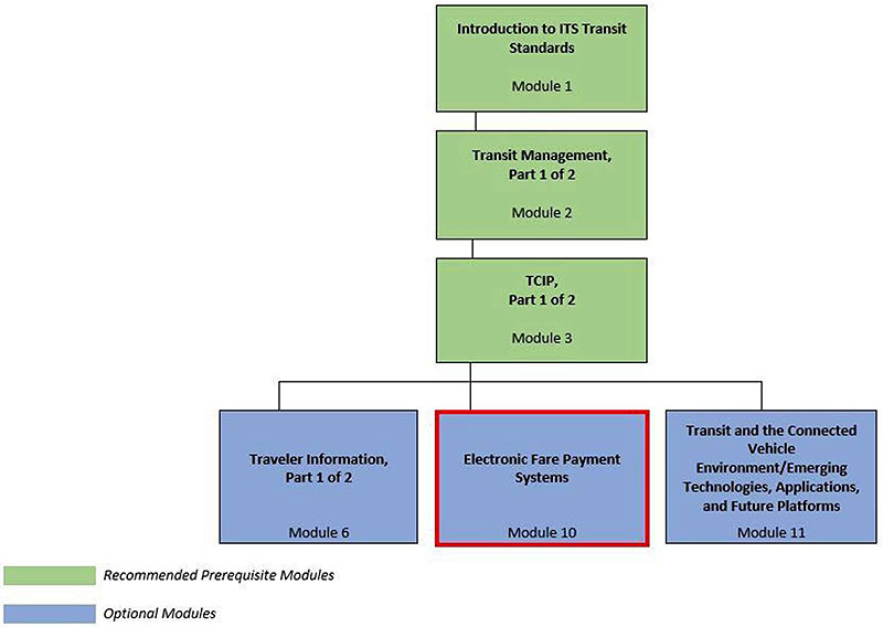
(Extended Text Description: Curriculum Path for Decision Maker: A graphical illustration indicating the sequence of training modules and where this module fits in. Each module is represented by a box with the name of the module in it and a flow chart showing the logical flow of the modules with the current module boxed in red. The first three boxes are green and aligned horizontally, green signifying "Recommended Pre-requisites." The first box is "Introduction to ITS Transit Standards, Module 1." Below that, connected by a line, is a box with the text "Transit Management, Part 1 of 2." Below that, connected by a line, is a box with the text, "TCIP, Part 1 of 2." From here, the lines branch out into three text boxes that are horizontally sequenced and are in blue, signifying "Optional Modules." These three boxes are: "Traveler Information, Part 1 of 2", "Electronic Fare Payment Systems" outlined in red, and "Transit and the Connected Vehicle Environment/Emerging Technologies, Applications, and Future Platforms.")
Slide 11:
Curriculum Path (Project Manager)
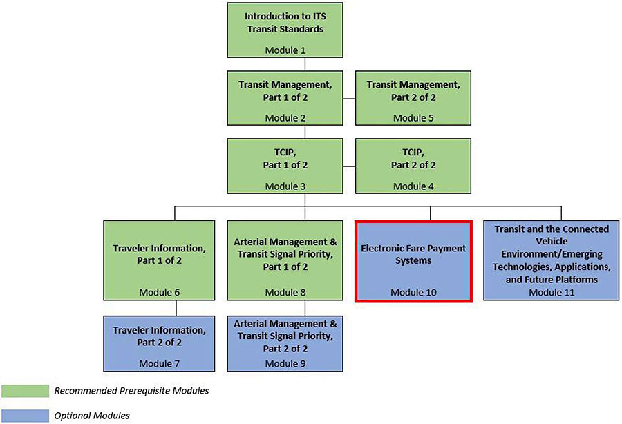
(Extended Text Description: Curriculum Path for Project Manager: A graphical illustration indicating the sequence of training modules and where this module fits in. Each module is represented by a box with the name of the module in it and a flow chart showing the logical flow of the modules with the current module boxed in red. The first three horizontally sequenced boxes are green. The first box is "Introduction to ITS Transit Standards, Module 1." Below that, connected by a line, is a box with the text "Transit Management, Part 1 of 2." To the right of this box, is "Transit Management, Part 2 of 2". Below that "Transit Management, Part 1 of 2", connected by a line, is a box with the text, "TCIP, Part 1 of 2." To the right of this box, is "TCIP, Part 2 of 2." From here, the lines branch out into four text boxes that are horizontally sequenced. The first two: "Traveler Information, Part 1 of 2" and "Arterial Management & Transit Signal Priority, Part 1 of 2" are green; the last two are "Electronic Fare Payment Systems" outlined in red, and "Transit and the Connected Vehicle Environment/Emerging Technologies, Applications, and Future Platforms." Below "Traveler Information, Part 1 of 2," is the text box "Traveler Information, Part 2 of 2" coded in blue. Below "Arterial Management & Transit Signal Priority, Part 1 of 2", is the text box "Arterial Management & Transit Signal Priority, Part 2 of 2," coded in blue.)
Slide 12:
Curriculum Path (Project Engineer)
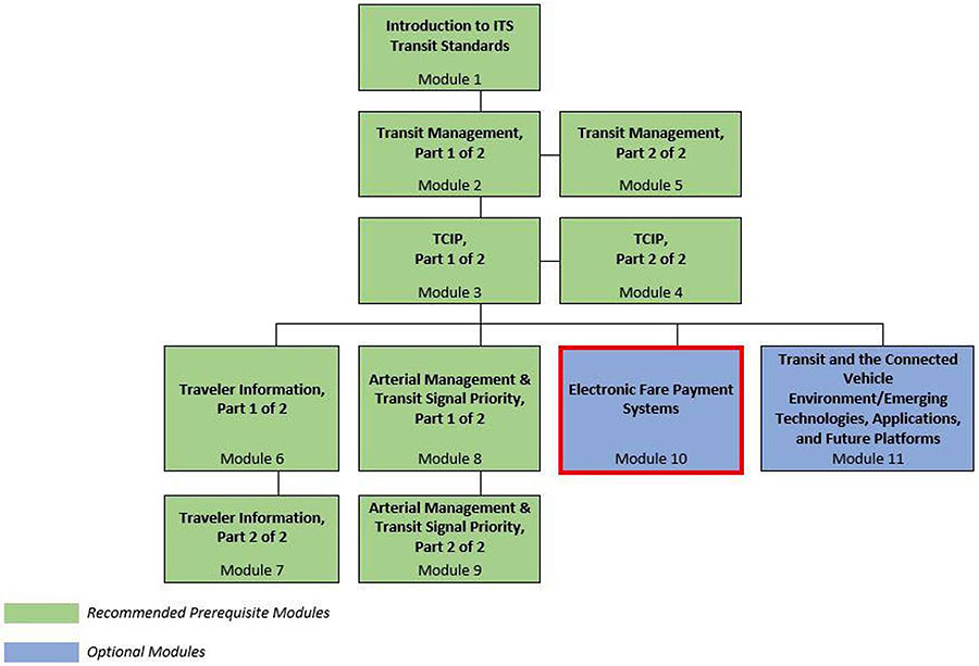
(Extended Text Description: Curriculum Path for Project Engineer: A graphical illustration indicating the sequence of training modules and where this module fits in. Each module is represented by a box with the name of the module in it and a flow chart showing the logical flow of the modules with the current module boxed in red. The first three horizontally sequenced boxes are green. The first box is "Introduction to ITS Transit Standards, Module 1." Below that, connected by a line, is a box with the text "Transit Management, Part 1 of 2." To the right of this box, is "Transit Management, Part 2 of 2". Below that "Transit Management, Part 1 of 2", connected by a line, is a box with the text, "TCIP, Part 1 of 2." To the right of this box, is "TCIP, Part 2 of 2." From here, the lines branch out into four text boxes that are horizontally sequenced. The first two: "Traveler Information, Part 1 of 2" and "Arterial Management & Transit Signal Priority, Part 1 of 2" are green; the last two are "Electronic Fare Payment Systems" outlined in red, and "Transit and the Connected Vehicle Environment/Emerging Technologies, Applications, and Future Platforms." Below "Traveler Information, Part 1 of 2," is the text box "Traveler Information, Part 2 of 2" coded in green. Below "Arterial Management & Transit Signal Priority, Part 1 of 2", is the text box "Arterial Management & Transit Signal Priority, Part 2 of 2," coded in green.)
Slide 13:
Learning Objective #1
-
Recognize and identify:
- Commonly used terms in electronic fare payment
- The characteristics (e.g. architecture, features, costs, media, benefits, and challenges) of the leading electronic fare payment methodologies
Slide 14:
Learning Objective #2
-
Recognize and identify:
- The applicable national and international standards, rules, and regulations for electronic fare payment systems and the benefits of applying those standards, rules, and regulations
- Where the lack of applicable standards create logical gaps in fare payment architectures that must be addressed by the agency
Slide 15:
Learning Objective #3
-
Evaluate the options for electronic fare payment by:
- Assessing the unique implementation issues of the transit industry
- Applying case studies of leading-edge electronic fare payment technologies and methodologies
Slide 16:
Learning Objective #4
-
Apply newly developed skills to:
- Assess agency requirements in order to facilitate selection of a methodology and architecture for electronic fare payment
- Support the procurement and implementation of a new electronic fare payment system or existing system enhancement
Slide 17:
Learning Objective #1
Recognize and Identify:
- Commonly used terms in electronic fare payment
- The characteristics (e.g. architecture, features, costs, media, benefits, and challenges) of the leading electronic fare payment methodologies
Slide 18:
Learning Objective #1
Typical Electronic Fare Payment System (EFPS) Architecture and Components
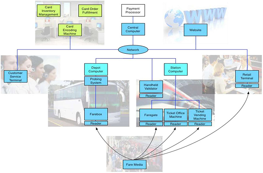
(Extended Text Description: Typical architecture and components for an Electronic Fare Payment System: A diagram that identifies many of the most common components and services associated with an Electronic Fare Payment System each represented by a colored box that is connected by a colored line to the other boxes. Each of those colored boxes is located within one of seven groups, each of which is represented by a photograph or other graphical image. The first group, in the upper left corner of the diagram is represented by the photograph of an office scene of desks, chairs and computer monitors. Within this group are boxes labeled "Card Inventory Management", "Card Order Fulfillment", and "Card Encoding Machine". The second group, in the upper right corner, is represented by the image of a world globe to the left of the letters "www". It includes only one box labeled "Website". Between these two groups are boxes labeled "Payment Processor" and "Central Computer" and underneath those two boxes is an oblong labeled "Network". The next group, on the far left side, centered vertically, is represented by the photo of people working in a call center. Within this group is one box labeled "Customer Service Terminal". The group to the immediate right of the call center box is represented by the photo of a large bus. Within this group are four boxes labeled, from top to bottom, "Depot Computer", "Probing System", "Farebox", and "Reader". The next group to the right is represented by the photo of a train. Within this group are six boxes labeled, from top to bottom and left to right, "Station Computer", "Handheld Validator", "Reader", "Faregate", "Ticket Office Machine", and "Ticket Vending Machine". Under each of the last three boxes is a box labeled "Reader". To the right of that group is the photo of a retail store that includes a sales clerk in front of a cash register and two customers. Within this group are two boxes labeled "Retail Terminal" and "Reader". The final group at the bottom center of the diagram is represented by the photo of a large group of people boarding a tram. Within this group is one box labeled "Fare Media".)
Slide 19:
Learning Objective #1
Commonly Used Terms
Electronic Fare Payment System (EFPS)
- System that performs automated calculation, collection, recording, and reporting of fare payment transactions for rides on a public transit system
- Uses some form of electronic validation and, in most instances, electronic media (e.g. contactless smart card, magnetic stripe card, card emulated through mobile phone)
Slide 20:
Learning Objective #1
Commonly Used Terms EFPS Types
-
Account-based System
- Comparable to credit card systems - payment media is only a token to access centrally stored/managed account record
-
Card-based System
- Most common form of EFPS
- Fare product data is stored in card memory and read/updated by readers
-
Open Payment System
- System where contactless bankcards are the primary fare media
- Often combined with either card- or account-based systems to support prepaid fare products
Slide 21:
Learning Objective #1
Commonly Used Terms
Fare Policy
-
The set of rules for a transit agency that define how, when, and by what methods passengers pay fares including:
- The base price of fares paid using cash or stored value
- The available types and retail price of passes
- The discounts on fares and passes offered to individuals and groups that qualify for participation in special (discounted) fare programs
- The rules and cost for making transfers from one transit agency vehicle to another as part of a single journey
Slide 22:
Learning Objective #1
Commonly Used Terms
System Architecture
The set of all components of an EFPS and the methods used to send information between those components.
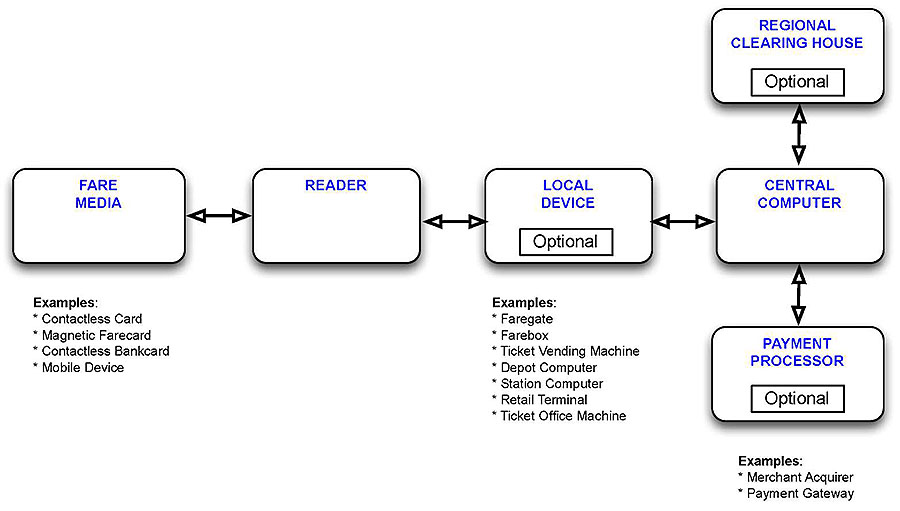
(Extended Text Description: System Architecture, relevant description: A simple, box diagram that illustrates the components of a typical Electronic Fare Payment System that perform the bulk of the work in receiving, processing and storing fare payment data. There are four white boxes in the diagram laid out in the straight line, each connected by arrows. These boxes, from left to right, are labeled "Fare Media", "Reader", "Local Device", and "Central Computer". There are two additional white boxes, one above and one below the Central Computer box and each of those boxes is also connected to the Central Computer box by arrows. The box on the top is labeled "Regional Clearing House" and the box on the bottom is labeled "Payment Processor". Within each of the Regional Clearing House, Payment Processor, and Local Device boxes is another smaller white box labeled "Optional". A list of examples appears below the Fare Media, the Local Device, and the Payment Processor boxes.)
Slide 23:
Learning Objective #1
Commonly Used Terms
Fare Value Options
-
Closed Loop (Value)
- Prepaid stored funds that can be used only for payment of fares
-
Open Loop (Value)
- Prepaid or postpaid funds that can be used to make fare payments as well as purchases at other retail merchants
Slide 24:
Learning Objective #1
EFPS Architecture
Data Elements and Flow
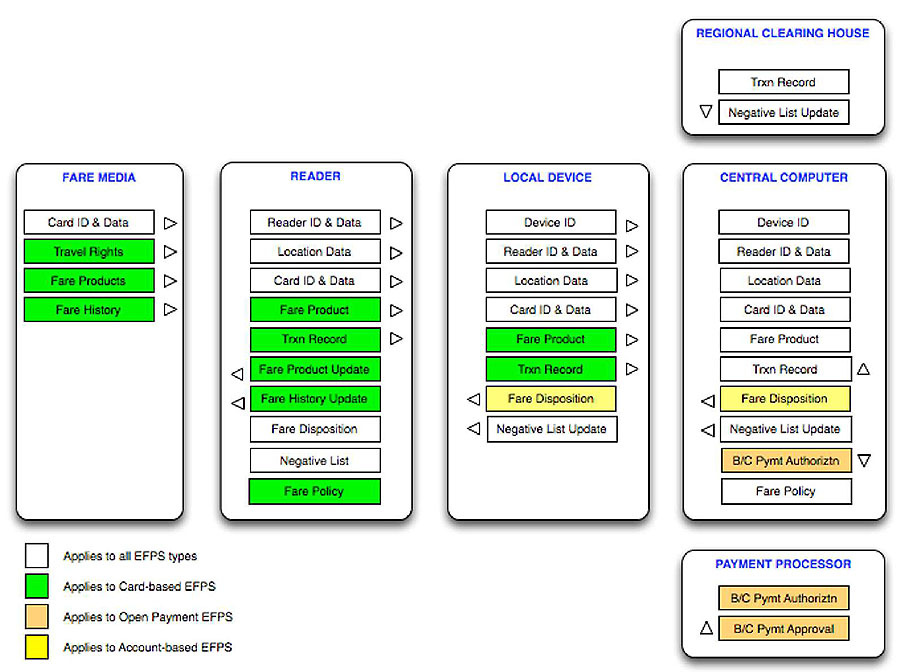
(Extended Text Description: Data Elements and Flow: An expanded version of the System Architecture diagram shown on Slide #22 that identifies the specific types of data elements that flow through Electronic Fare Payment Systems. These boxes have been color-coded to identify, where applicable, data elements that are unique to one of the three most common Electronic Fare Payment System types: Card-based (in green), Open Payment (in Orange) and Account-based (in Yellow). Data elements appearing in a white box are common to all types. A key explaining this color-coding scheme appears in the lower left corner of the diagram. The boxes listed the data elements are aligned vertically within each of the six larger boxes, which, as described on Slide #19, are labeled "Fare Media, "Reader", "Local Device", "Central Computer", "Regional Clearing House", and "Payment Processor". Within the Fare Media box is one white box at the top labeled "Card ID & Data" and three green boxes below labeled "Travel Rights", "Fare Products", and "Fare History". Within the Reader box are three white boxes at the top labeled "Reader ID & Data", "Location Data", and "Card ID & Data" followed by four green boxes labeled "Fare Product", "Trxn (Transaction) Record", "Fare Product Update", and "Fare History Update". Below these are two additional white boxes labeled "Fare Disposition" and "Negative List" followed by one green box labeled "Fare Policy". Within the Local Device box are four white boxes at the top labeled "Device ID", "Reader ID & Data", "Location Data", and "Card ID & Data" followed by two green boxes labeled "Fare Product" and "Trxn Record". Below those is one yellow box labeled "Fare Disposition" and the bottom is one white box labeled "Negative List Update". Within the Central Computer box are six white boxes at the top labeled "Device ID", "Reader ID & Data", "Location Data", "Card ID & Data", "Fare Product", and "Trxn Record" followed by a yellow box labeled "Fare Disposition". Below that is one white box labeled "Negative List Update", an orange box labeled "B/C (bankcard) Pymt (payment) Authoriztn (authorization)", and a white box labeled "Fare Policy". Within the Regional Clearing House box are two white boxes labeled "Trxn Record" and "Negative List Update". Within the Payment Processor box are two orange boxes labeled "B/C Pymt Authoriztn" and "B/C Pymt Approval".)
Slide 25:
Learning Objective #1
Card-Based Systems
Feature Overview
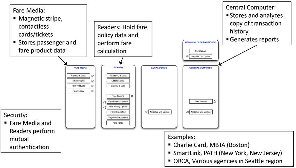
(Extended Text Description: Open Payment Systems Feature Overview: A further expansion of the System Architecture diagram shown on Slides #22 and 24 that describes certain key components of the system in greater detail or by examples that appear in text boxes most of which have an arrow pointing to one of the original boxes in the diagram. The first text box points to the Fare Media box. The first bulleted item lists "magnetic stripe" and "contactless cards / tickets" as examples of the types of fare media that are used in this type of system. The second bulleted item explains that fare media "stores passenger and fare product data". The second text box points to the Reader box. It explains that the readers "hold fare policy data and perform fare calculation". The third text box points to the Central Computer box. The first bulleted item explains that the central computer "stores and analyzes a copy of transaction history" and it "generates reports". The fourth text box is labeled Security. It contains one bulleted item that explains that the primary security in this type of system "fare media and readers perform mutual authentication". The fifth text box is labeled Examples. The list of bulleted examples of card-based systems are the "Massachusetts Bay Transportation Authority (MBTA) Charlie Card program, Boston", the "Port Authority of New York & New Jersey Trans-Hudson (PATH) SmartLink program, New York and New Jersey", and the "One Regional Card for All (ORCA) program, which various participating agencies in the Seattle, Washington region".)
Slide 26:
Learning Objective #1
Card-Based Systems
Benefits and Disadvantages
Key Benefits
-
For agencies:
- Offered by all leading fare collection system integrators and suppliers
- Well-developed set of best practices
- Access points can operate despite loss of communications to central system
- Secure transactions with fast transaction time
-
For passengers:
- Variety of prepaid fare products available for purchase and use
Slide 27:
Learning Objective #1
Card-Based Systems
Benefits and Disadvantages
Disadvantages
-
For agencies:
- Adding (purchasing) fare products requires special devices to write data to fare media
- Requires broad network for physical distribution of fare media and fare products
- Central system not updated in real-time - can't be used as reliable source of passenger account data
- Access points require substantial intelligence and processing power - more expensive to buy and maintain
Slide 28:
Learning Objective #1
Card-Based Systems
Technical Challenges
- Automatic replenishment (e.g. auto load) of fare products is a complex process that may require several days to complete
- Fare policy changes require delivery of software changes to every field device
- Card data security is paramount - breach of security scheme can compromise system's financial accuracy/reliability
Slide 29:
Learning Objective #1
Open Payment Systems
Feature Overview
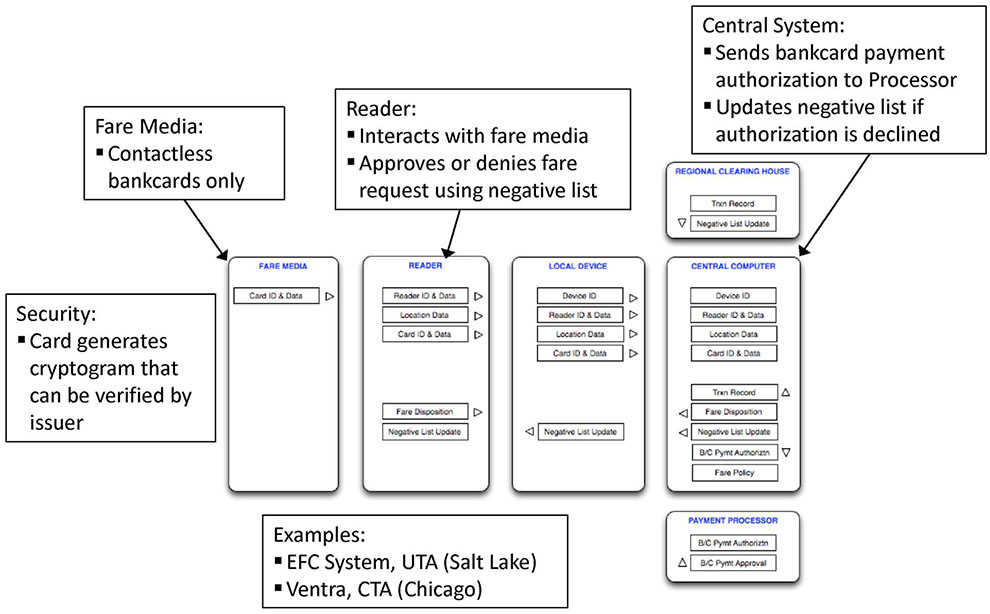
(Extended Text Description: Card-based Systems Feature Overview: A further expansion of the System Architecture diagram shown on Slide #22 that describes certain key components of the system in greater detail or by examples that appear in text boxes most of which have an arrow pointing to one of the original boxes in the diagram. The first text box points to the Fare Media box. The first bulleted item lists "contactless bankcards only". The second text box points to the Reader box. It explains that the reader "interacts with fare media" and "approves or denies the fare payment request using a negative list". The third text box points to the Central Computer box. The first bulleted item explains that the central system "sends bankcard payment authorization requests to a Merchant Processor" and it "updates the negative list if authorization is declined". The fourth text box is labeled Security. It contains one bulleted item that explains that for the primary security in this type of system the "card generates a cryptogram that can be verified by the card’s issuer". The fifth text box is labeled Examples. The list of bulleted examples of open payment systems are the "Electronic Fare Collection (EFC) system of the Utah Transit Authority (UTA) in Salt Lake City, Utah" and the "Ventra program of the Chicago Transit Authority (CTA) in Chicago, Illinois".)
Slide 30:
Learning Objective #1
Open Payment Systems
Feature Overview
EFPS type which relies on bank-issued cards as the fare media. Initial fare processing is performed by the field devices and final authorization and settlement are performed later by the central computer.
Central System
- Receives and processes batches of fare payment transactions
- Generates bankcard payment authorization requests and transmits to acquirer
- May aggregate two or more payments from the same card to reduce processing cost
Slide 31:
Learning Objective #1
Open Payment Systems
Feature Overview (cont.)
Access Points
- Approve or deny fare payments based on negative list of "bad" bankcards
- Provide approval/decline to passenger
Fare Media
- Contactless bankcards
- Mobile devices emulating a contactless bankcard using an near field communication-compliant (NFC) communications protocol
Slide 32:
Learning Objective #1
Open Payment Systems
Benefits and Disadvantages
Key Benefits
-
For agencies:
- Reduces or eliminates need for agency-issued fare media
- May transfer portion of passenger servicing to bankcard issuers
- Reduced complexity of software in field devices and central system
- Reduced need for ticket vending machines and/or retail network
-
For passengers:
- No advanced knowledge of fare structure required
- No special fare media required
Slide 33:
Learning Objective #1
Open Payment Systems
Benefits and Disadvantages
Disadvantages
-
For agencies:
- No support for prepaid fare products
- Little or no capability to perform real-time card authentication
- Use of negative lists in Open Payment System is the subject of patent disputes
- Only small percentage of passengers have contactless bankcard
-
For passengers:
- Passengers may be approved or denied incorrectly due to lag time for updates to negative list in field devices
Slide 34:
Learning Objective #1
Open Payment Systems
Technical Challenges
- Frequent and quick updates to negative list in field devices is critical
- Card/reader interface defined by networks - may not support the fast transaction times typically required within the transit industry
Slide 35:
Learning Objective #1
Account-Based Systems
Feature Overview
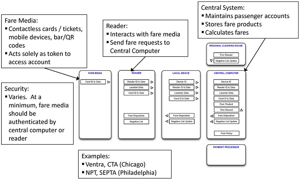
(Extended Text Description: (Animation) Account-based Systems Feature Overview: A further expansion of the System Architecture diagram shown on Slide #22 that describes certain key components of the system in greater detail or by examples that appear in text boxes most of which have an arrow pointing to one of the original boxes in the diagram. The first text box points to the Fare Media box. The first bulleted item is "contactless cards / tickets, mobile devices, and bar and quick reference (QR) codes". The seconded bulleted item explains that the fare media "acts solely as a token to access account information". The second text box points to the Reader box. It explains that the reader "interacts with the fare media" and "sends fare requests to the Central Computer". The third text box points to the Central Computer box. The three bulleted items are "maintains passenger accounts", "stores fare products", and "calculates fares". The fourth text box is labeled Security. It contains one bulleted item that explains that the primary security scheme "Varies but, at a minimum, fare media should be authenticated by the central computer or the reader". The fifth text box is labeled Examples. The list of bulleted examples of card-based payment systems are the "Ventra program of the Chicago Transit Authority (CTA) in Chicago, Illinois" and the" New Payment Technology (NPT) program of the Southeastern Pennsylvania Transit Authority (SEPTA) in Philadelphia, Pennsylvania".)
Slide 36:
Learning Objective #1
Account-Based Systems
Benefits and Disadvantages
Key Benefits
-
For agencies:
- Fare policy changes only need to be made at the central computer
- Software in readers is less complex and easier to maintain
- Any networked device can be used to sell fare products
-
For passengers:
- Wider sales network for fare products
- Fare products and payments history accessible via any networked device
Slide 37:
Learning Objective #1
Account-Based Systems
Benefits and Disadvantages
Disadvantages
-
For agencies:
- Offline readers must process fare requests using local negative or positive list
- Online, real-time fare processing is infeasible without fast, reliable communications
- New method with comparatively few systems in revenue service
Slide 38:
Learning Objective #1
Account-Based Systems
Technical Challenges
- High speed, reliable communications from stations and vehicles
- Complex logic to process offline transactions once uploaded
Slide 39:
Learning Objective #1
EFPS Methodologies
Comparative Analysis
| Methodology | Primary Security Scheme | Fare Processing Logic | Fare Products & Passenger Rights | Fare Media |
|---|---|---|---|---|
| Account-based |
|
|
|
|
| Card-based |
|
|
|
|
| Open Payment |
|
|
|
|
Slide 40:

Slide 41:
Learning Objective #1
Which of the following is a feature of only an account-based EFPS?
Answer Choices
- The central computer sends a negative list to each reader
- Data stored on card is read and updated by the reader
- Contactless bankcards are the primary fare media
- The central computer is responsible for fare calculation
Slide 42:
Learning Objective #1
Review of Answers
 a) The central computer sends a negative list to each reader
Incorrect. This feature is applicable to all three types of EFPS.
b) Data stored on card is read and updated by the reader
Incorrect. This feature is unique to a card-based EFPS.
c) Contactless bankcards are the primary fare media
Incorrect. This feature applies primarily to an open payment EFPS.
 d) The central computer is responsible for fare calculation
Correct! In an account-based EFPS, the central computer holds all of the passenger, fare product and history data and fare processing rules and uses this information to calculate the fare due for each fare payment.
Slide 43:
Learning Objective #1
Summary of Learning Objective #1
After completing this section of the module, the reviewer should be able to recognize and identify:
- Commonly used terms in electronic fare payment
- The characteristics (e.g. architecture, features, costs, media, benefits, and challenges) of the leading electronic fare payment methodologies
Slide 44:
Learning Objective #2
Learning Objective #2
Recognize and Identify:
- The applicable national and international standards, rules, and regulations for electronic fare payment systems and the benefits of applying them
- Where the lack of applicable standards create logical gaps in fare payment architectures that must be addressed by the agency
Slide 45:
Learning Objective #2
Standards, Rules, and Regulations
Overview
- Certain national and international standards and specifications are applicable to an EFPS
- Applicability of these standards and specifications varies by EFPS types
- These standards and specifications do not prescribe an end-to-end EFPS architecture and may not ensure interoperability of systems or components
Slide 46:
Learning Objective #2
Standards, Rules, and Regulations
ISO/IEC 14443 Identification cards - Contactless integrated circuit cards - Proximity cards
- Widely adopted standard for short range communications between cards and readers
- Applies to physical and virtual cards and readers
-
Applicable to:
- All EFPS methodologies
Slide 47:
Learning Objective #2
Standards, Rules, and Regulations
ISO/IEC 7816 Identification cards, Integrated circuit cards
- Defines physical dimensions of smart cards and a common set of instructions that should be supported
- Combined with ISO/IEC 14443, helps to promote interoperability
-
Applicable to:
- All EFPS methodologies
Slide 48:
Learning Objective #2
Standards, Rules, and Regulations
ISO/IEC 18092 Information technology, Telecommunications and information exchange between systems, Near Field Communication, Interface and Protocol (NFCIP-1)
- Better known as "NFC"
- Defines methods to enable short-range communications between mobile phones and readers
-
Applicable to:
- EFPS methodologies where mobile devices may be used
Slide 49:
Learning Objective #2
Standards, Rules, and Regulations
ISO/IEC 21481, Information technology, Telecommunications and information exchange between systems, Near Field Communication Interface and Protocol -2 (NFCIP-2)
- Additional standard under the "NFC" umbrella
- Defines short-range communications between "active" and "passive" devices
-
Applicable to:
- All EFPS methodologies where mobile devices may be used
Slide 50:
Learning Objective #2
Standards, Rules, and Regulations
ISO/IEC 8583, Financial transaction card originated messages, Interchange message specifications
- Defines the format and content of messages exchanged for bankcard transactions
-
Applicable to:
- All EFPS methodologies where bankcards are accepted for fare payments or for purchases of any kind
Slide 51:
Learning Objective #2
Standards, Rules, and Regulations
ISO/TR 14806 Intelligent transport systems, Public transport requirements for the use of payment applications for fare media
- Technical report (TR) that defines the requirements for payment applications on multi-application, contactless bankcard used for fare payments
- Describes the possibility of adding the capability of storing and updating fare-specific data in card memory
-
Applicable to:
- Open payment EFPS, including those that also support card-based fare payments
Slide 52:
Learning Objective #2
Standards, Rules, and Regulations
ISO 24014 Interoperable Fare Management Systems (IFMS)
- Defines standards and rules for development and operation of a regional) fare system
-
Applicable to:
- Primarily card-based EFPS
Slide 53:
Learning Objective #2
Standards, Rules, and Regulations
Europay, MasterCard, Visa (EMV) Specifications
- Provides specifications for chip-based bankcards and merchant payment terminals
- Widely adopted internationally
- U.S. adoption began in 2013
-
Applicable to:
- Open payment EFPS
- Any EFPS that accepts bankcards for payment of any purchases
Slide 54:
Learning Objective #2
Standards, Rules, and Regulations
Bankcard Network Contactless Credit and Debit Card Specifications
-
Card networks' contactless card products used in the U.S. include: ° American Express expressPay
- Discover ZIP
- MasterCard PayPass
- Visa payWave
- Separate applications are required in the reader (or Central Computer) to enable communications with these cards.
- Rules for card acceptance also vary by network
Slide 55:
Learning Objective #2
Standards, Rules, and Regulations
Payment Card Industry Data Security Standards (PCI DSS)
- Defines standards for securing bankcard data
-
Applicable to:
- All EFPS methodologies where bankcards are accepted in any form
Slide 56:
Learning Objective #2
Standards, Rules, and Regulations
American Public Transportation Association (APTA) Contactless Fare Media System (CFMS) Standard
- National standard for regional, card-based EFPS programs
- Developed by APTA
-
Applicable to:
- Card-based EFPS
Slide 57:
Learning Objective #2
Standards, Rules, and Regulations
Transit Communications Interface Profiles (TCIP)
- Developed to be the ITS standard for transit management communications
- Introduces a standard framework for exchanging data among various transit modules and systems
- Includes a library of data elements, data frames, messages, and dialogs using Extensible Markup Language (XML).
Slide 58:
Learning Objective #2
Standards, Rules, and Regulations
Integrated Transport Smartcard Organization (ITSO)
- UK specification/standard for cards and terminals used in a card-based EFPS
Calypso
- European standard for card-based EFPS where the media uses a microprocessor-based chip to ensure exceptionally fast and secure transactions.
- One of the most widely adopted standards for EFPS with implementations in Europe, China, Canada, the United States, and Latin America
CIPURSE
- An open standard for card-based fare collection systems focused primarily on the card data structure and card to reader security scheme.
Slide 59:
Learning Objective #2
EFPS Architecture
Gaps Created by the Lack of Applicable Standards
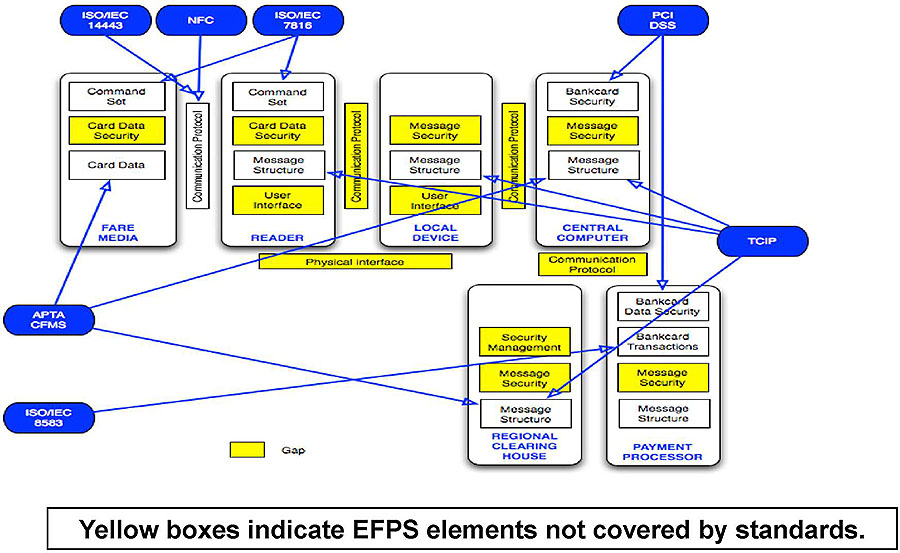
(Extended Text Description: EFPS Architecture, Gaps created by the lack of applicable standards is a simple, block diagram that identifies the elements of electronic fare payment systems (represented by white text boxes) are covered by national or international standards, regulations or specifications (represented by blue oblong shapes) and, separately, which elements are not covered (represented by yellow text boxes). Most of the white and yellow text boxes are grouped within six larger white boxes, which appear in two horizontal rows, one with four boxes and the second, below the first, with two boxes. There is either a white or a yellow text box in between each pair of the larger white boxes. These text boxes represent the communication protocol and/or physical connection that is used to send messages between the systems components that are represented by those larger white boxes. Blue arrows connect the blue oblongs to the white text boxes to identify those system elements that are covered by the standard, regulation or specification listed within the blue oblong. From top to bottom and left to right, the larger white boxes are labeled as "Fare Media", "Reader", "Local Device", "Central Computer", "Regional Clearing House", and "Payment Processor". The first two blue oblongs are labeled "ISO/IEC 14443" and "NFC" and have arrows connecting them to a white text box labeled "Communication Protocol" between the larger white boxes labeled "Fare Media" and "Reader". The next blue oblong is labeled "ISO/IEC 7816" has two arrows connecting it to two different white text boxes each labeled "Command Set". One of those text boxes is in the larger white box labeled "Fare Media" and the second is in the larger white box labeled "Reader". The next blue oblong is labeled "PCI DSS" and has two arrows, one connecting it to a white text box labeled "Bankcard Security" in the larger white box labeled "Central Computer" and the second connecting it to the white text box labeled "Bankcard Data Security" in the larger white box labeled "Payment Processor". The next blue oblong located on the right side of the diagram is labeled "TCIP" and has four arrows, one connecting it to the white text box labeled "Message Structure" in the larger white box labeled "Central Computer", a second one connecting it to the white text box labeled "Message Structure" in the larger white box labeled "Local Device", a third one connecting it to a white text box labeled "Message Structure" in the larger white box labeled "Reader" and the fourth one connecting it to a white text box labeled "Message Structure" in the larger white box labeled "Regional Clearing House". The next blue oblong located on the left side of the diagram is labeled "APTA CFMS" and has three arrows, one connecting it to a white text box labeled "Card Data" in the larger white box labeled "Fare Media", a second one connecting it to the white text box labeled "Message Structure" in the larger white box labeled "Central Computer", and a third one connecting it to the white text box labeled "Message Structure" in the larger white box labeled "Regional Clearing House". The last blue oblong located in the lower left corner of the diagram labeled "ISO/IEC 8583" has one arrow connecting it to the white text box labeled "Bankcard Transactions" in the larger white box labeled "Payment Processor". There is a long text box at the bottom of the diagram, which reads "Yellow boxes indicate EFPS elements not covered by standards".)
Slide 60:
Learning Objective #2
Key Gaps in Existing Standards
| Gap | Gap Description | Mitigation Tactics |
|---|---|---|
| Inter-system security |
|
|
| Component "plug-and-play" |
|
|
| New media integration |
|
|
| User Interface |
|
|
| Other |
|
|
Slide 61:

Slide 62:
Learning Objective #2
Which of the following EFPS features does the Transit Communications Interface Protocol (TCIP) cover?
Answer Choices
- Local device to central computer message structure
- Card data structure
- Card to reader communication protocol
- Physical requirements for contactless fare card
Slide 63:
Learning Objective #2
Review of Answers
a) Local device to central computer message structure
Correct! The content and structure of messages exchanged between a field (local) device and the central computer are included in the TCIP standards.
b) Card data structure
Incorrect. This feature is defined in APTA CFMS.
c) Card to reader communications protocol
Incorrect. This feature is defined in ISO/IEC 14443.
d) Physical requirements for a contactless fare card
Incorrect. The feature is defined in ISO/IEC 7816.
Slide 64:
Learning Objective #2
Summary of Learning Objective #2
After completing of this section of the module, the reviewer should be able to recognize and identify:
- The applicable national and international standards, rules, and regulations for EFPS and the benefits of applying them
- Where the lack of applicable standards create logical gaps in fare payment architectures that must be addressed by the agency
Slide 65:
Learning Objective #3
Learning Objective #3
Evaluate the Options for Electronic Fare Payment by:
- Assessing the unique implementation issues of the transit industry
- Applying case studies of leading-edge electronic fare payment technologies and methodologies
Slide 66:
Learning Objective #3
Account-Based System
Fare Payment Transaction Flow
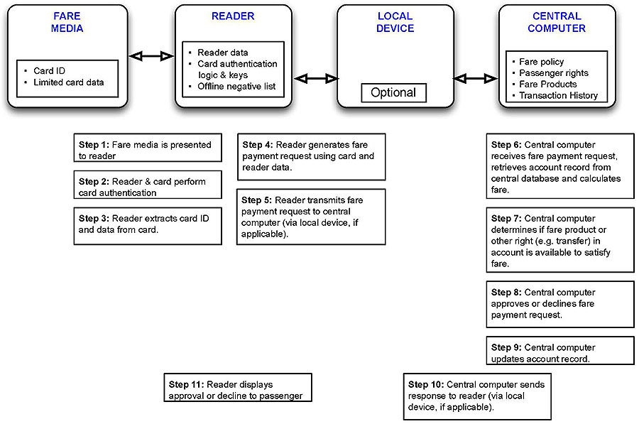
(Extended Text Description: Account-based System Fare Payment Transaction Flow is a simple box diagram that uses four of the same system elements included in the diagram previously shown on Slide 22 to illustrate the flow of data through those system elements in an account-based system. There are four large square boxes aligned horizontally across the top of the diagram labeled "Fare Media", "Reader", "Local Device", and "Central Computer". Each of these boxes has a smaller white text box inside of it and is connected to the box next to it with a horizontal line with arrows on each end. The text box within the Fare Media box has two bulleted items: "Card ID" and "Limited card data". The text box within the Reader box has three bulleted items: "Reader data", "Card authentication logic & keys", and "Offline negative list". The text box within the Local Device reads "Optional". The text box within the Central Computer box has four bulleted items: "Fare policy", "Passenger rights", "Fare products", and "Transaction History". Aligned in three columns below the large square boxes are nine white text boxes that describe the flow of data. There are two additional white text boxes at the bottom of the diagram. The first white text box reads "Step 1: Fare media is presented to reader". The second white text box located directly below the first reads "Steps 2: Reader & card perform card authentication". The third white text box located directly below the second reads "Step 3: Reader extracts card ID and data from card". The fourth white text box located to the right of the Step 1 box reads "Step 4: Reader generates fare payment request using card and reader data". The fifth white text box located directly below the fifth reads "Step 5: Reader transmits fare payment request to central computer (via local device, if applicable)". The sixth white text box located to the right of the Step 5 box reads "Step 6: Central computer receives fare payment request, retrieves account record from central database and calculates fare". The seventh white text box located directly below the sixth box reads "Step 7: Central computer determines if fare product or other right (e.g. transfer) in account is available to satisfy fare". The eight white text box located directly below the seventh box reads "Step 8: Central computer approves or declines fare payment request". The ninth white text box located directly below the eight box reads "Step 9: Central computer updates account record". A tenth white text box positioned below and to the left of the ninth box reads "Step 10: Central computer sends response to reader (via local device, if applicable). The eleventh white text box located to the left of the tenth box reads "Step 11: Reader displays approval or decline to passenger".)
Slide 67:
Learning Objective #3
Account-Based System
Implementation Considerations
Fare Payment Processing
- Option 1: Online/Real-time s Reader sends fare request to central computer s Central computer makes decision and responds s Need solution for offline conditions
- Option 2: Offline/Batch s Reader makes decision using negative list, etc. s Central computer calculates fare later
Security
- Fare media authentication is essential
Network
- High-speed, reliable communications required (Option 1)
- Buses probably use cellular
Slide 68:
Learning Objective #3
Account-Based System
Implementation Considerations (cont.)
Fare Media Distribution
- N/A
Fare Products
- With Option 2, negative or positive list in readers must be updated quickly or else passenger may be unable to pay fare
Applicable Standards
- ISO/IEC 14443
- ISO/IEC 7816
- ISO/IEC 8583
- TCIP
Slide 69:
Learning Objective #3
Account-Based System
Operational Benefits
Various forms of fare media could be supported
- Contactless smartcard
- Limited use ticket
- Mobile phone displaying bar/QR code
- Printed bar/QR code
- Mobile phone using NFC
"Bring Your Own Device"
- Reduces cost of fare media distribution and replacement
- Mobile device is both fare media and virtual vending machine
Slide 70:
Learning Objective #3
Account-based System
Operational Benefits (cont.)
Fare products are digital
- Sale and "delivery" via any networked device
- Instantaneous "delivery" (buy now, use now)
- Auto loads easily accommodated
- Lost cards easily blocked and replaced
Centralized fare policy and rules
- Changes required only in central system
- No need to send updates to every field device
- Greater processing power and storage at central system supports more complex fare policies
Slide 71:
Learning Objective #3
Card-Based System
Fare Payment Transaction Flow
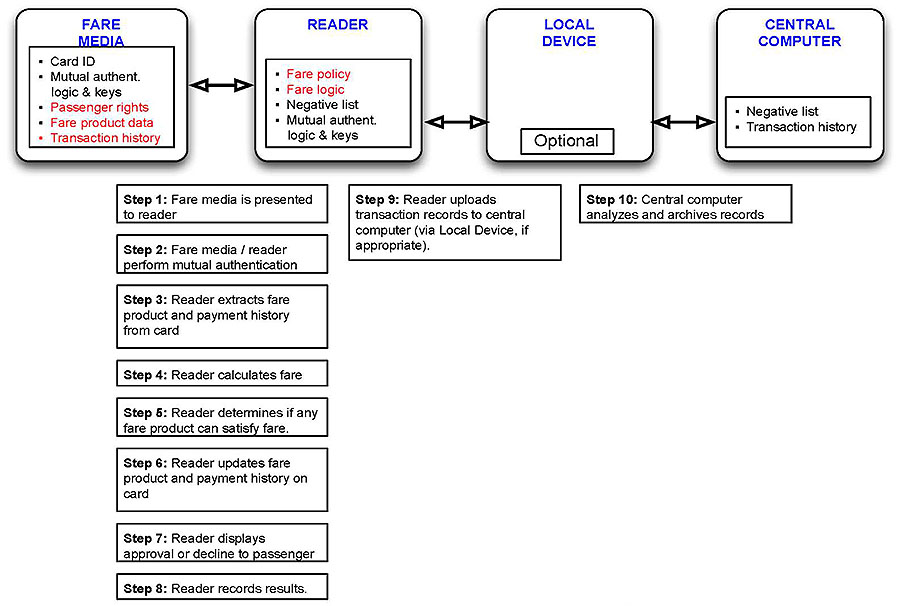
(Extended Text Description: Card-based System Fare Payment Transaction Flow is a simple box diagram that uses the same structure described for slide 66. This diagram illustrates and describes the flow of fare payment data in a card-based system. There are the same four large square boxes aligned horizontally across the top of the diagram labeled "Fare Media", "Reader", "Local Device", and "Central Computer". The text box within the Fare Media box has five bulleted items: "Card ID", "Mutual authentication logic & keys", "Passenger rights", "fare product data" and "Transaction history". The text box within the Reader box has four bulleted items: "Fare policy", "Fare logic", "Negative list", and "Mutual authentication logic & keys". The text box within the Local Device reads "Optional". The text box within the Central Computer box has two bulleted items: "Negative list" and "Transaction history". Below those square boxes are 10 white text boxes aligned in three columns. The first column includes the following text boxes and text: "Step 1: Fare media is presented to reader", "Step 2: Fare media / reader perform mutual authentication", "Step 3: Reader extracts fare product and payment history from card", "Step 4: Reader calculates fare", "Step 5: Reader determines if any fare product can satisfy fare", "Step 6: Reader updates fare product and payment history on card", "Step 7: Reader displays approval or decline to passenger", and "Step 8: Reader records results". The second column includes one text box with the text: "Step 9: Reader uploads transaction records to central computer (via Local Device, if appropriate)". The third column includes one text box with the text: "Step 10: Central computer analyzes and archives records".)
Slide 72:
Learning Objective #3
Card-Based System
Implementation Considerations
Fare Payment Processing
- Robust application in readers to perform fare calculation
- Fare policy changes require software download to every field device
- Transaction time under 350ms to avoid "transaction tearing" Security
- Comprehensive security key management and distribution process
- Frequent updates required to negative list in field devices Network
- Minimal bandwidth required (to support batch uploading of transaction data)
Slide 73:
Learning Objective #3
Card-Based System
Implementation Considerations (cont.)
Fare Media Distribution
- Special devices required to read/write data on fare media Fare Products
- Online purchases challenging to accommodate Applicable Standards
- ISO/IEC 14443
- ISO/IEC 7816
- APTA CFMS
- NFC
- ISO/IEC 8583
- TCIP
Slide 74:
Learning Objective #3
Card-Based System
Operational Benefits
"Bring your own device"
- Mobile phone using NFC interface and custom-designed app
- Reduces cost of fare media distribution and replacement
System works offline
- Offline field devices can continue to process fare payments for long periods of time
Extensive experience
- Method supported by every major EFPS supplier
- Many different cards and devices proven in revenue service
Slide 75:
Learning Objective #3
Open Payment System
Fare Payment Transaction Flow
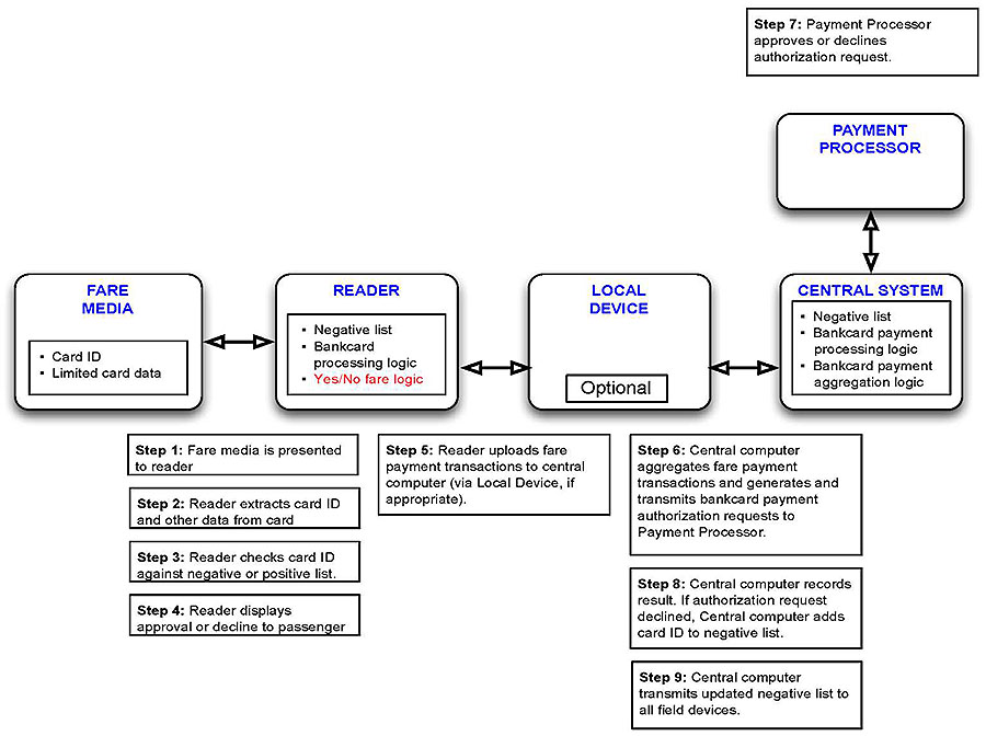
(Extended Text Description: Open Payment System Fare Payment Transaction Flow is a simple box diagram that uses the same structure described for slide 66. This diagram illustrates and describes the flow of fare payment data in an open payment system. There are the same four large boxes aligned horizontally across the top of the diagram labeled "Fare Media", "Reader", "Local Device", and "Central Computer" plus one additional box labeled "Payment Processor". The text box within the Fare Media box has two bulleted items: "Card ID" and "Limited card data". The text box within the Reader box has three bulleted items: "Negative list", and "Bankcard processing logic" and "Yes/No fare logic". The text box within the Local Device reads "Optional". The text box within the Central Computer box has three bulleted items: "Negative list", "Bankcard payment processing logic" and "Bankcard payment aggregation logic". Below those square boxes are eight white text boxes aligned in three columns. A ninth white text box is located above and to the right of the larger white boxes. The first column includes the following text boxes and text: "Step 1: Fare media is presented to reader", "Step 2: Reader extracts card ID and other data from card", "Step 3: Reader checks card ID against negative or positive list", "Step 4: Reader displays approval or decline to passenger". The second column includes one text box with the text: "Step 5: Reader payment transactions to central computer (via Local Device, if appropriate)". The third column includes three text boxes with the text: "Step 6: Central computer aggregates fare payment transactions and generates and transmits bankcard payment authorization requests to Payment Processor", "Step 8: Central computer records result, if authorization request declined. Central computer adds card ID to negative list", and "Step 9: Central computer transmits updated negative list to all field devices".
The last text box reads: "Step 7: Payment Processor approves or declines authorization request.)
Slide 76:
Learning Objective #3
Open Payment System
Implementation Considerations
Fare Payment Processing
- Fare policy is restricted to value-based payments
Security
- U.S.-issued contactless bankcards lack an offline card authentication solution
- Frequent updates to negative list stored in field devices is required
Network
-
Reliable communications required
- Readers to central computer
- Central computer to Payment Processor
Slide 77:
Learning Objective #3
Open Payment System
Implementation Considerations (cont.)
Fare Media
- Program relies on continued bank and passenger use of contactless bankcards
- Solution needed for passengers without bankcards
Fare Products
- Not applicable. Method only supports value-based fares.
Applicable Standards
- ISO/IEC 14443
- ISO/IEC 7816
- EMV-contactless
- NFC
- ISO/IEC 8583
- TCIP
Slide 78:
Learning Objective #3
Open Payment System
Operational Benefits
"Bring your own device"
- Bank-issued credit, debit, or prepaid card
- Mobile phone using NFC interface and mobile app to emulate bank-issued card
- Reduces cost of fare media distribution and replacement
System works offline
- Offline field devices can continue to process fare payments for short periods of time
Slide 79:

Slide 80:
Learning Objective #3
Case Study
Chicago Transit Authority (CTA) Ventra Program
EFPS type: Multi-agency, Account-based with Open Payment
-
Standard features:
- Extensive vending machine and retailer network for cards and fare products
-
Unique requirements:
- Outsourcing of 100% of system operations, maintenance, and risk
- Aggressive (six-month) transition from old (card-based) system to new
- Exclusive use of contactless bankcards as fare media
-
Fare media:
- Primary: Contactless prepaid MasterCard debit card
- Secondary: Bank-issued, contactless credit and debit
-
Implementation issues:
- Negative public and media reaction to fees and early system glitches
- Unreliable communications network prevents real-time fare calculation
Slide 81:
Learning Objective #3
Case Study
CTA Ventra Program Key Benefits
- $5M+ annual savings in fare collection system operations
- Transfer of most financial and technology risks to vendor for life of contract
-
Increased passenger convenience
- Significant increase in card and fare product distribution network
- Fare product purchases via website
- All fare products available through every sales channel
- Ability to use contactless bankcard in lieu of cash fares on buses
Slide 82:
Learning Objective #3
Case Study
Greater Toronto Area (GTA) Presto Program
EFPS type: Regional Card-based with Open Payment
-
Standard features:
- Contactless card readers
- Extensive vending machine and retailer network for card and fare product sales
-
Unique requirements:
- Multi-agency, multi-mode regional program
- Open interfaces allowing for variety of vendors to provide field equipment
- Open payment included
Slide 83:
Learning Objective #3
Case Study
Greater Toronto Area (GTA) Presto Program (cont.)
-
Fare media:
- Primary: Clearinghouse-issued contactless fare card
- Secondary: Bank-issued, contactless credit and debit
-
Implementation issues:
- Initial reluctance of largest agency in region (Toronto Transit Authority) to participate
- Negative public and media reaction to delays, cost overruns and change orders
- System glitches and delays with first medium-sized agency implementation
Slide 84:
Learning Objective #3
Case Study
GTA Presto Program Key Benefits
- Creation of regional fare payments program
- Reduced bus operator responsibilities for fare product validation
- Reduced cash fares
-
Increased passenger convenience
- Significant increase in card and fare product distribution network
- Ability to use contactless bankcard in lieu of cash fares on buses and in stations
Slide 85:
Learning Objective #3
Case Study
Jacksonville Transit Authority (JTA) Star Card
EFPS type: Single agency, Card-based system
-
Standard features:
- Single agency program
- Vending machines and equipment for retailer network
-
Unique requirements:
- Reduce bus operator responsibilities for fare collection
- Eliminate paper transfer tickets and associated thefts
- Simultaneous introduction of fare policy change from zone to flat fare
-
Fare media:
- Primary: Agency-issued contactless fare card
- Limited use tickets
-
Implementation issues:
- Unanticipated operating costs (new staff, TVM servicing)
- Lack of broad distribution network for cards and fare products
- Lead time to purchase smart cards
Slide 86:
Learning Objective #3
Case Study
JTA Star Card Key Benefits
- Reduced transaction time (-63%)
-
Reduced boarding time (-23.5%)
- Average driving time reduction of 1 hour per route
- 1% reduction in pollution
-
Reduced operating costs
- $60,000 in annual fuel savings
- Ticket printing costs: $86,000+ annual savings
-
Fare policy flexibility
- Greater variety of fare media and fare products
- Reduced fare evasion and transfer ticket theft
- Increased passenger convenience
- Better data
Slide 87:

Slide 88:
Learning Objective #3
Which type of EFPS only supports value-based fares?
Answer Choices
- Card-based EFPS
- Open Payment EFPS
- Account-based EFPS
- All of the above
Slide 89:
Learning Objective #3
Review of Answers
a) Card-based EFPS
Incorrect. A card-based EFPS can support a wide variety of fare products including passes and various forms of prepaid stored value.
b) Open Payment EFPS
Correct! Open payment EFPS only accept contactless bankcards which hold only card-specific data that can't be changed. Since other forms of fare products would either need to be recorded in card memory or associated with an account in the central system an open payment EFPS can only support value-based fares.
c) Account-based EFPS
Incorrect. This type of EFPS can support a virtually unlimited variety of prepaid fare products, including passes.
d) All of the above
Incorrect. Card-based EFPS and account-based EFPS can each support a wide variety of prepaid fare products, including passes.
Slide 90:
Learning Objective #3
Summary of Learning Objective #3
After completing this section of the module, the reviewer should be able to:
-
Evaluate the options for electronic fare payment by:
- Assessing the unique implementation issues of the transit industry
- Applying case studies of the leading EFPS methodologies
Slide 91:
Learning Objective #4
Learning Objective #4
Apply Newly Developed Skills to:
- Assess agency requirements in order to facilitate selection of a methodology and architecture for electronic fare payment
- Support the procurement and implementation of a new, electronic fare payment system or existing system enhancement
Slide 92:
Learning Objective #4
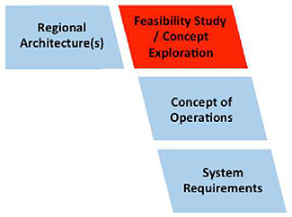
Systems Engineering Process Vee Diagram
Requirements Development and Analysis
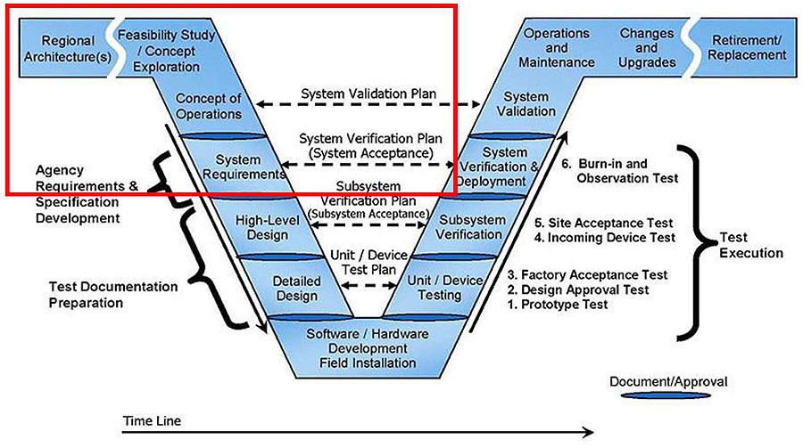
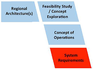
(Extended Text Description: Systems Engineering Process Vee Diagram Requirements Development and Analysis is a diagram with a series of text laid out in the shape of the letter vee, relevant author's description: This diagram identifies the standard steps that should be included in the planning, specification, and implementation of any type of system. Four of these steps are applicable to the development of specifications for a new electronic fare payment system or an upgrade to an existing electronic fare payment system. These steps are labeled "Regional Architecture(s)", "Feasibility Study / Concept Exploration", "Concept of Operations", and "System Requirements". The other 10 steps in the Vee Diagram and the other text elements on the inside and outside of the vee are not applicable to this module.)
Slide 93:
Learning Objective #4
Applying the SEP
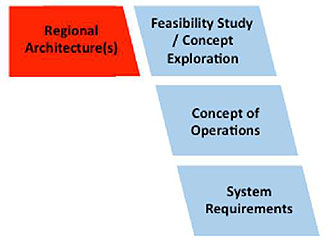
Regional Architecture and Implications
- Define the vision and objectives for the regional fare payments program
-
Define the program scope
- Infrastructure
- Fare products and/or services
- Procurement process and vendor contract(s)
-
Define program governance
- Stakeholders roles and responsibilities
- System validation and certification
- Revenues and expense sharing (if applicable)
- Regional fare policy management
- Vendor management
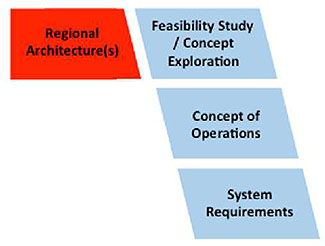
(Extended Text Description: The four applicable steps of the Systems Engineering Process Vee Diagram from Slide 92 are presented as a graphic in the lower right corner of this slide. The first of those steps, labeled "Regional Architecture(s)" is highlighted in red to indicate that the information on this slide pertains to that step.)
Slide 94:
Learning Objective #4
Applying the SEP
Regional Architecture and Implications (cont.)
-
Define regional requirements
- System architecture, interfaces and security
- Financial settlement and clearing
- Performance levels
(Extended Text Description: The four applicable steps of the Systems Engineering Process Vee Diagram from Slide 92 are presented as a graphic in the lower right corner of this slide. The first of those steps, labeled "Regional Architecture(s)" is highlighted in red to indicate that the information on this slide pertains to that step.)
Slide 95:
Learning Objective #4
Applying the SEP
Feasibility Study / Concept Exploration
During this phase, the agency should develop a high level concept for its EFPS.
-
Core Objectives
- Identify and document business, technical and schedule constraints
- Document key program objectives and desired implementation schedule
- Make preliminary EFPS type selection
- Verify project feasibility and identify key risks
- Secure management buy-in and sponsorship
-
Key Steps
- Define evaluation criteria
- Identify and evaluate alternative concepts
- Evaluate alternatives
(Extended Text Description: The four applicable steps of the Systems Engineering Process Vee Diagram from Slide 92 are presented as a graphic in the lower right corner of this slide. The second of those steps, labeled "Feasibility Study / Concept Exploration" is highlighted in red to indicate that the information on this slide pertains to that step.)
Slide 96:
Learning Objective #4
Applying the SEP
Concept of Operations
During this phase, a preliminary decision on EFPS type is made.
-
Core Objectives
- Define high level requirements for all stakeholders
- Establish roles and responsibilities
- Ensure common understanding of system concept and requirements
- Establish system performance and program success metrics
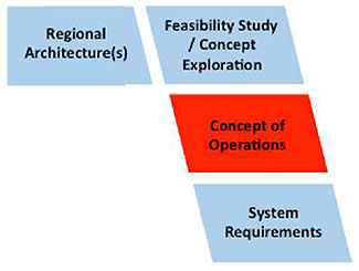
(Extended Text Description: The four applicable steps of the Systems Engineering Process Vee Diagram from Slide 92 are presented as a graphic in the lower right corner of this slide. The third of those steps, labeled "Concept of Operations" is highlighted in red to indicate that the information on this slide pertains to that step.)
Slide 97:
Learning Objective #4
Applying the SEP
Concept of Operations (cont.)
-
Key Steps
- Identify and document all stakeholders
- Form the core program team
-
Develop an initial Concept of Operations
- Identify business and operational issues of the existing system
- Identify and analyze the cost components of the existing system
- Review existing fare policy and define a strategy for future policy evolution
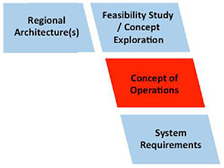
(Extended Text Description: The four applicable steps of the Systems Engineering Process Vee Diagram from Slide 92 are presented as a graphic in the lower right corner of this slide. The third of those steps, labeled "Concept of Operations" is highlighted in red to indicate that the information on this slide pertains to that step.)
Slide 98:
Learning Objective #4
Applying the SEP
Requirements Definition
-
Requirements should:
- Clearly define a business or functional need
- Identify business (e.g. budgetary, schedule) and technical constraints
- Define performance service levels
- Be consistent with program objectives
- Encourage supplier innovation
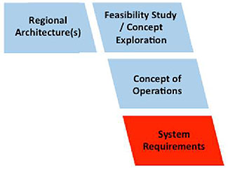
(Extended Text Description: The four applicable steps of the Systems Engineering Process Vee Diagram from Slide 92 are presented as a graphic in the lower right corner of this slide. The third of those steps, labeled "System Requirements" is highlighted in red to indicate that the information on this slide pertains to that step.)
Slide 99:
Learning Objective #4
Applying the SEP
Requirements Definition (cont.)
-
Requirements should NOT:
- Prescribe a particular technology or solution, except when required due to technical constraints
- Use undefined terms, abbreviations, or abbreviations
- Be based on vague or undocumented assumptions
(Extended Text Description: The four applicable steps of the Systems Engineering Process Vee Diagram from Slide 92 are presented as a graphic in the lower right corner of this slide. The third of those steps, labeled "System Requirements" is highlighted in red to indicate that the information on this slide pertains to that step.)
Slide 100:
Learning Objective #4
Applying the SEP
Requirements Definition (sample)
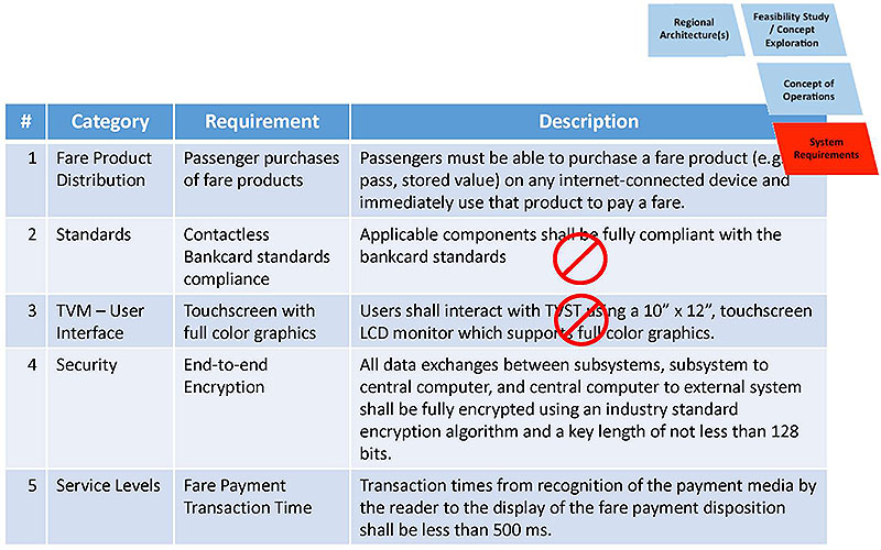
(Extended Text Description: The four applicable steps of the Systems Engineering Process Vee Diagram from Slide 92 are presented as a graphic in the upper right corner of this slide. The third of those steps, labeled "Concept of Operations" is highlighted in red to indicate that the information on this slide pertains to that step. Applying the SEP Requirements Definition (sample) is a table of sample requirements used to show examples of requirements that meet and those that don’t meet the standards defined in the System Engineer Process for well-written requirements. The raw table data itself is included below at the end of this description. It has four columns with the headers "#", "Category", "Requirement", and "Description". There are five rows below these headings numbered 1 through 5 in the # column. The cells in Row #1 read "Fare Product Distribution", "Passenger purchases of fare products", and "Passengers must be able to purchase a fare product (e.g. pass, stored value) on any internet-connected device and immediately use that product to pay a fare". The cells in Row #2 read "Standards", "Contactless Bankcard standards compliance", and "Applicable components shall be fully compliant with the bankcard standards". The cells in Row #3 read "TVM – User Interface", "Touchscreen with full color graphics", and "Users shall interact with TVMs using a 10" x 12", touchscreen LCD monitor which support full color graphics". The cells in Row #4 read "Security", "End-to-end Encryption", and "All data exchanges between subsystems, subsystem to central computer, and central computer to external system shall be fully encrypted using an industry standard encryption algorithm and a key length of not less than 128 bits. The cells in Row #5 read "Service Levels", "Fare Payment Transaction Time", and "Transaction times from recognition of the payment media by the reader to the display of the fare payment disposition shall be less than 500 ms."
Raw table data included below in table format:
| # | Category | Requirement | Description |
|---|---|---|---|
| 1 | Fare Product Distribution | Passenger purchases of fare products | Passengers must be able to purchase a fare product (e.g.: pass, stored value) on any internet-connected device and immediately use that product to pay a fare. |
| 2 | Standards | Contactless Bankcard standards compliance | Applicable components shall be fully compliant with the bankcard standards |
| 3 | TVM - User Interface | Touchscreen with full color graphics | Users shall interact with TVST using a 10" x 12", touchscreen LCD monitor which supports full color graphics. |
| 4 | Security | End-to-end Encryption | All data exchanges between subsystems, subsystem to central computer, and central computer to external system shall be fully encrypted using an industry standard encryption algorithm and a key length of not less than 128 bits. |
| 5 | Service Levels | Fare Payment Transaction Time | Transaction times from recognition of the payment media by the reader to the display of the fare payment disposition shall be less than 500 ms. |
Slide 101:
Learning Objective #4
Selecting the Correct EFPS Type
EFPS Characteristics
| Methodology | Primary Security Scheme | Fare Processing Logic | Fare Products & Passenger Rights | Fare Media |
|---|---|---|---|---|
| Account-based |
|
|
|
|
| Card-based |
|
|
|
|
| Open Payment |
|
|
|
|
Slide 102:
Learning Objective #4
Selecting the Correct EFPS Type
Matching Requirements to EFPS Characteristics
Sample Requirement: Passengers must be able to purchase a fare product (e.g. pass, stored value) on any internet-connected device and immediately use that product to pay a fare.
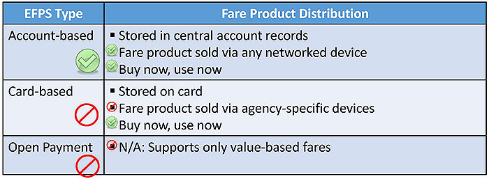
(Extended Text Description: Selecting the Correct EFPS Type Matching requirements to EFPS characteristics is a table used to illustrate how agency requirements are matched to a particular type of Electronic Fare Payment System type. Above the table is the text of a sample requirement that reads, "Passengers must be able to purchase a fare product (e.g. pass, stored value) on any internet-connected device and immediately use that product to pay a fare". The raw table data itself is included below at the end of this description. The header of the first column is "EFPS Type" and the header of the second column is "Fare Product Distribution". There are three rows below the headers with the labels "Account-based", "Card-based", and "Open Payment". The Fare Product Distribution column in the Account-based row has three bulleted items that read: "Stored in central account records", "Fare product sold via any networked device", "Buy now, use now". There is a green circle with a check mark in the middle next to the last two of these bulleted items. The circles indicate that these characteristics are a compliant with the sample requirement. A larger green circle with a check mark in the first column indicates that an account-based system’s characteristics would be able to meet the sample requirement. The Fare Product Distribution column in the Card-based row has three bulleted items that read: "Stored on card", "Fare product sold via agency-specific devices", and "Buy now, use now". There is a red circle with a red line across the center next to the second of these characteristics to indicate that it is not compliant with the sample requirement. There is a green circle with a check mark in the middle next to the third characteristic to indicate that it compliant with the sample requirement. There is a larger red circle with a red line across the center in the first column to indicate that at least one of these card-based system characteristics fails to meet the sample requirement. The Fare Product Distribution column in the Open Payment row has one bulleted item that reads: "N/A: Supports only value-based fares". There is a red circle with a red line across the center next to this characteristic to indicate that it is not compliant with the sample requirement. There is a larger red circle with a red line across the center in the first column to indicate that at least one of these open payment system characteristics fails to meet the sample requirement.
Raw table data included below in table format:
| EFPS Type | Fare Product Distribution |
|---|---|
| Account-based |
|
| Card-based |
|
| Open Payment |
|
Slide 103:
Learning Objective #4
Selecting the Correct EFPS Type
Matching Requirements to EFPS Characteristics
Sample Requirement: Devices at points of entry (e.g. faregates, fareboxes) shall use security mechanisms (e.g. authentication) that prevent the use of counterfeit payment media before allowing entry/boarding.
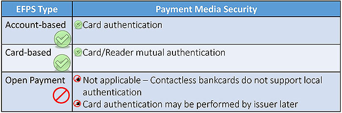
(Extended Text Description: Selecting the Correct EFPS Type Matching requirements to EFPS characteristics is a table similar to that used on Slide 102 to illustrate how agency requirements are matched to a particular type of Electronic Fare Payment System type. Above the table is the text of a sample requirement that reads "Devices at points of entry (e.g. faregates, fareboxes) shall use security mechanisms (e.g. authentication) that prevent the use of counterfeit payment media before allowing entry/boarding." The raw table data itself is included below at the end of this description. The column headers of this table are "EFPS Type" and "Payment Media Security". The row labels are identical to those on the table on Slide 102. The Payment Media Security column in the Account-based row has one bulleted item that reads: "Card Authentication". There is a green circle with a check mark in the middle next to that characteristic to indicate it is compliant with the sample requirement. A larger green circle with a check mark in the first column indicates that this account-based system characteristic meets the sample requirement. The Payment Media Security column in the Card-based row has one bulleted item that reads: "Card/Reader mutual authentication". There is a green circle with a check mark in the middle next to that characteristic to indicate that it is compliant with the sample requirement. There is a larger green circle with a check mark in the middle in the first column to indicate that this card-based system characteristic meets the sample requirement. The Payment Media Security column in the Open Payment row has two bulleted items that read: "Not applicable – Contactless bankcards do not support local authentication: and "Card authentication may be performed by issuer later". There is a red circle with a line across the center next to each of these characteristics to indicate that each is not compliant with the sample requirement. There is a larger red circle with a line across the center in the first column to indicate that at least one of these open payment system characteristics fails to meet the sample requirement.
Raw table data included below in table format:
| EFPS Type | Payment Media Security |
|---|---|
| Account-based |
|
| Card-based |
|
| Open Payment |
|
Slide 104:
Learning Objective #4
Selecting the Correct EFPS Type
Matching EFPS Features to Requirements
Sample Requirement: The EFPS shall only accept for fare payments contactless bankcards that adhere to the ExpressPay, PayPass, payWave, or ZIP specifications.
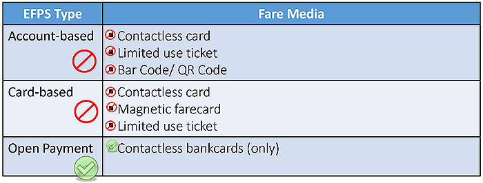
(Extended Text Description: Selecting the Correct EFPS Type Matching requirements to EFPS characteristics is a table similar to that used on Slide 102 to illustrate how agency requirements are matched to a particular type of Electronic Fare Payment System type. Above the table is the text of a sample requirement that reads, "The EFPS shall only accept for fare payments contactless bankcards that adhere to the ExpressPay, PayPass, payWave or ZIP specifications." The raw table data itself is included below at the end of this description. The column headers of this table are "EFPS Type" and "Fare Media". The row labels are identical to the tables on slides 102 and 103. The Fare Media column in the Account-based row has three bulleted items that read: "Contactless card", "Limited use ticket", and "Bar Code/QR Code". There is a red circle with a line across the center next to each of those bulleted items to indicate that each is not compliant with the sample requirement. A larger red circle with a line across the center in the first column indicates that at least one of these account-based system characteristics fails to meet the sample requirement. The Fare Media column in the Card-based row has three bulleted items that read: "Contactless card", "Magnetic fare card", and "Limited use ticket". There is a red circle with a line across the center next to each of these characteristics to indicate that each is not compliant with the sample requirement. There is a larger red circle with a line across the center in the first column to indicate that at least one of these card-based system characteristics fails to meet the sample requirement. The Fare Media column in the Open Payment row has one bulleted item that reads: "Contactless bankcards (only)". There is a green circle with a checkmark in the middle next to this characteristic to indicate that is compliant with the sample requirement. There is a larger green circle with a checkmark in the middle in the first column to indicate that this open payment characteristic meets the sample requirement.
Raw table data included below in table format:
| EFPS Type | Fare Media |
|---|---|
| Account-based |
|
| Card-based |
|
| Open Payment |
|
Slide 105:
Learning Objective #4
Selecting the Correct EFPS Type
Matching EFPS Features to Requirements
Sample Requirement: Fare payment processing shall support a variety of fare policies including, but not limited to, the use of pass products, transfer rights, and discounts to special fare program participants.
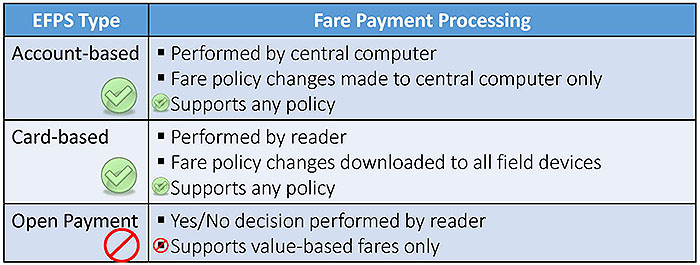
(Extended Text Description: Selecting the Correct EFPS Type Matching requirements to EFPS characteristics is a table similar to that used on Slide 102 to illustrate how agency requirements are matched to a particular type of Electronic Fare Payment System type. Above the table is the text of a sample requirement that reads "Fare payment processing shall support a variety of fare policies including, but not limited to, the use of pass products, transfer rights and discounts to special fare program participants". The raw table data itself is included below at the end of this description. The column headers of this table are "EFPS Type" and "Fare Payment Processing". The row labels are identical to the tables on slides 102, 103 and 104. The Fare Payment Processing column in the Account-based row has three bulleted items that read: "Performed by central computer", "Fare policy changes made to central computer only", and "Supports any policy". There is a green circle with a checkmark in the middle next to each of those bulleted items to indicate that each is compliant with the sample requirement. A larger green circle with a checkmark center in the middle in the first column indicates that these account-based system characteristics all meet the sample requirement. The Fare Payment Processing column in the Card-based row has three bulleted items that read: "Performed by reader", "Fare policy changes downloaded to all field devices", and "Supports any policy". There is a green circle with checkmark in the middle next to the third characteristics to indicate that it is compliant with the sample requirement. There is a larger green circle with a checkmark in the middle in the first column to indicate that one of these card-based system characteristics meets the sample requirement. The Fare Payment Processing column in the Open Payment row has two bulleted items that read: "Yes/No decision performed by reader" and "Supports value-based fares only". There is a red circle with a line across the center next to the second characteristic to indicate that it is not compliant with the sample requirement. There is a larger red circle with a line across the center in the first column to indicate that at least one of these open payment characteristics fails to meets the sample requirement.
Raw table data included below in table format:
| EFPS Type | Fare Payment Processing |
|---|---|
| Account-based |
|
| Card-based |
|
| Open Payment |
|
Slide 106:
Learning Objective #4
Selecting the Correct EFPS Type
Role of Security in an EFPS
-
A comprehensive security program is essential and should include:
- Fare media authentication
- Message protection
- Sensitive data storage and access rules
- Encryption key management and distribution
- System monitoring and testing
- Procedures for handling security breaches
-
Impacts of security breaches can be devastating
- Loss of revenue
- Loss of passenger confidence
- Security system upgrade/replacement costs
Slide 107:

Slide 108:
Learning Objective #4
Which of the following is an important consideration when defining security requirements for an EFPS?
Answer Choices
- Sensitive data protection
- Protection of cash while being transported to a bank
- On-board surveillance systems for bus vehicles
- Scheduling of daily fare payment reports
Slide 109:
Learning Objective #4
Review of Answers
a) Sensitive data protection
Correct! Protection of all sensitive, fare-related data is a critical concern for all transit agencies and must be carefully documented in the form of requirements when procuring an EFPS.
b) Protection of cash while being transported to a bank
Incorrect. Although important, protection of cash in not directly related to EFPS security.
c) On-board surveillance system for bus vehicles
Incorrect. Although important, such surveillance systems are not directly related to EFPS security.
d) Scheduling of daily fare payment reports
Incorrect. Although important, report printing and delivery is not directly related to EFPS security.
Slide 110:
Learning Objective #4
Summary of Learning Objective #4
After completing this section of the module, the reviewer should be able to apply newly developed skills to:
- Assess agency requirements in order to facilitate selection of a methodology and architecture for electronic fare payment
- Support the procurement and implementation of a new, electronic fare payment system or existing system enhancement
Slide 111:
What We Have Learned
- Electronic fare payment is the automated calculation, validation, collection, recording, and reporting of transactions using some form of electronic validation system and, in many instances, electronic media for payment of rides on a public transit system
- Electronic fare payment uses a variety of terms and abbreviations that are unique to the transit fare collection industry
- The three most common types of electronic fare payment systems are: card based, account-based, and open payment.
Slide 112:
What We Have Learned (cont.)
- Various national and international standards can be applied, however, there are significant gaps between these standards which must be addressed by agencies that are procuring a new or upgrade to an existing electronic fare payment system.
- Careful analysis of agency requirements is required in order to identify the correct EFPS type.
- Data security plays a key role in every EFPS but the methods will vary depending on the type of EFPS selected.
Slide 113:
Resources
- Your Smart Phone is Getting Smarter: https://www.its.dot.gov/pcb/t3/s110629 farecollection101.asp- content is no longer available./li>
- Put it on my Card: The Trend Towards Account-based Systems in Transit Systems: https://www.its.dot.gov/pcb/t3/s110118 openepay.asp- content is no longer available.
- The Future of Fare Collection: Contactless Fare Payment Systems based on CFMS Standards: https://www.its.dot.gov/pcb/t3/s071213 cfms.asp- content is no longer available.
- Putting the Pieces in Place: Seamless Regional Fare Payment Puts the Super in Southern California's "Super Region": https://www.its.dot.gov/pcb/t3/s120426 super region.asp- content is no longer available.
- TCRP BRD 57 Developing a Recommended Standard for Automated Fare Collection for Transit: https://www.tcrponline.org/PDFDocuments/TCRP RRD 57.pdf
See Student Guide for a more comprehensive list of resource documents and materials.
Slide 114:
Thank you for completing this module.