Transit Module 11: Transit and the Connected Vehicle Environment/Emerging Technologies, Applications, and Future Platforms
HTML of the PowerPoint Presentation
(Note: This document has been converted from a PowerPoint presentation to 508-compliant HTML. The formatting has been adjusted for 508 compliance, but all the original text content is included, plus additional text descriptions for the images, photos and/or diagrams have been provided below.)
Slide 1:
Slide 2:
Slide 3:
MODULE 11:
Transit and the Connected Vehicle Environment/Emerging Technologies, Applications, and Future Platforms
Slide 4:
Instructor
Raman K Patel, Ph.D., P.E.
President
RK Patel Associates, Inc.
Slide 5:
Learning Objectives
- Describe the connected vehicle (CV) environment
- Identify potential communications technologies that may be used in a transit CV environment
- Review the standards that support the transit CV environment
- Describe transit CV applications
- Identify the challenges and approaches to the successful deployment of transit CV applications
Slide 6:
Learning Objective 1
- Describe the Connected Vehicle (CV) Environment
Slide 7:
Connected Vehicle (CV) Environment
CV Environment
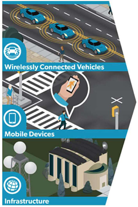
CV Environment Consists of:
-
V2X (V to Everything…)
- Vehicle to Vehicle (V2V)
- Vehicle to Infrastructure (V2I)
- Vehicle to Pedestrian (V2P)
CV Communications:
- Wireless
-
Mixture of:
- Short-range communications-open
- Remote communications, e.g. devices to Traffic Management Center (TMC)
- Safety/Mobility Applications
Slide 8:
Connected Vehicle (CV) Environment
Transportation Challenges addressed by CV
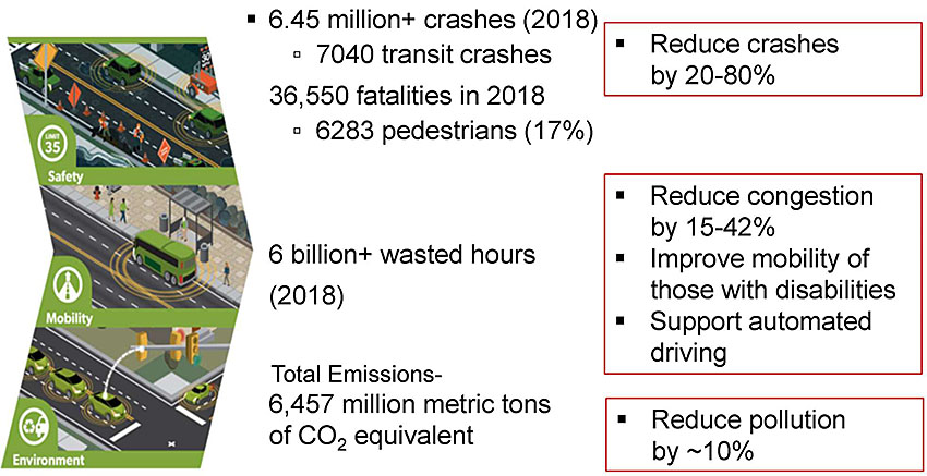
(Extended Text Description: On the left of this slide there is an image that depicts the three major benefits of the connected vehicle environment, namely Safety, Mobility, and Environment benefits.
To the right of Safety are the bullets:
-
6.45 million+ crashes (2018)
- 7040 transit crashes
-
36,550 fatalities in 2018
- 6283 pedestrians (17%)
To the right of these bullets is another bullet outlined in red:
- Reduce crashes by 20-80%
To the right of Mobility is the text:
6 billion+ wasted hours (2018)
To the right of that text are the following bullets outlined in red:
- Reduce congestion by 15-42%
- Improve mobility of those with disabilities
- Support automated driving
To the right of Environment is the text:
Total Emissions - 6,457 million metric tons of C02 equivalent
To the right of that text is the following bullet outlined in red:
- Reduce pollution by ~10%
Slide 9:
Connected Vehicle (CV) Environment
Vehicle-to-Pedestrian (V2P) Safety Challenges
- Transit vehicles operating in environments with non-transit vehicles and pedestrians pose a unique challenge, e.g., turning movements
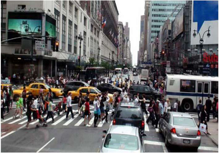
Source: NYCDOT
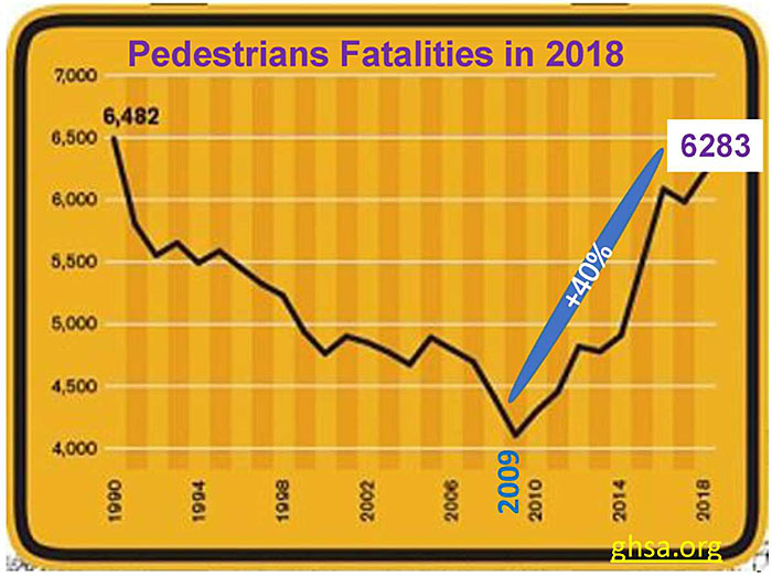
(Extended Text Description: Author's relevant notes: A graphic that shows pedestrian fatalities trend since 2009 to 2018, a 40% rise. Pedestrian fatalities in 2018 shown as 6283. The chart shows pedestrian fatality numbers from 1990 through 2018. The 1990 data point is labeled as 6,482 and is followed by a steep decline such that in 1992 the number is roughly 5,500, where it stabilizes for about five years before falling again until it reaches a low of just more than 4,000 in 2009. The drop then quickly reverses and increases to a projected 6,283 in 2018.)
Slide 10:
Areas of Applications-Transit Examples

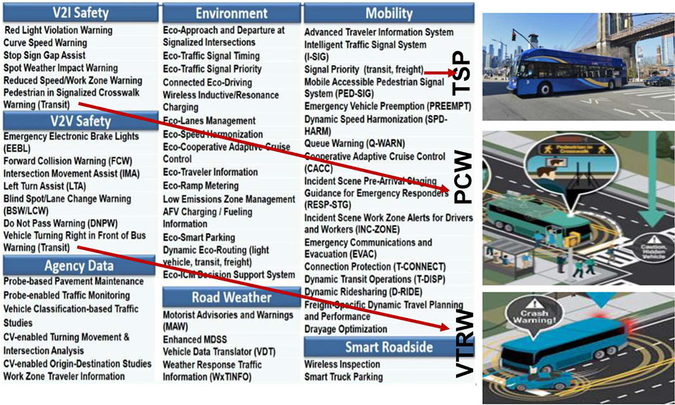
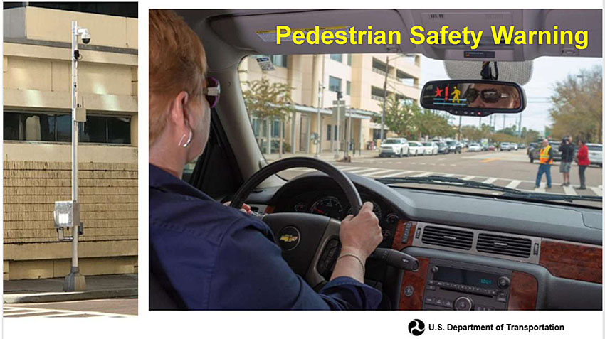
(Extended Text Description: Author's relevant description: The slide on left shows a USDOT list of CV applications, which includes Safety, Agency Data, Environment, Mobility and other areas. On the right side, three photos appear, first PCW in the middle which is connected to V2I Safety - Pedestrian in Signalized Crosswalk Warning (Transit) with a red arrow, followed by VTRW at bottom which is connected to V2I Safety - Pedestrian in Signalized Crosswalk Warning (Transit) with a red arrow, and at top TSP appears which is connected to V2V Safety - Vehicle Turning Right in Front of Bus Warning (Transit). Each has a red arrow pointing to it to indicate which photo is showing which application.)
Slide 11:
Connected Vehicle (CV) Environment
What has Changed (different)?
- Internal vehicle-based sensor data (speed, size, position…) not sufficient for reliable hazard detection-prediction
- "Connected vehicle" sensor data broadcasted externally to other vehicles in the vicinity, for issuing application-driven warning-alert
Cooperative ITS (C-ITS)
Slide 12:
Connected Vehicle (CV) Environment
Ad-Hoc Roadside Wireless Connectivity has Arrived
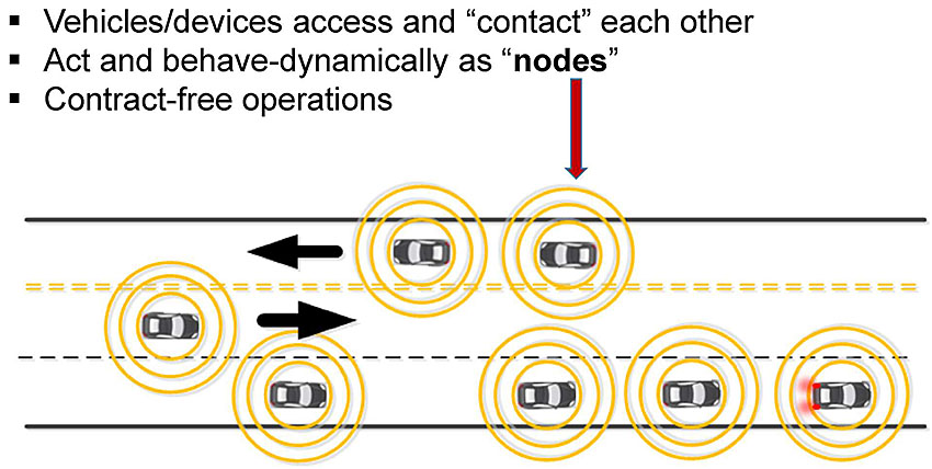
(Extended Text Description: This slide contains the follow bullet list with additional graphics:
- Vehicles/devices access and "contact" each other
- Act and behave dynamically as "nodes"
- Contract free operations
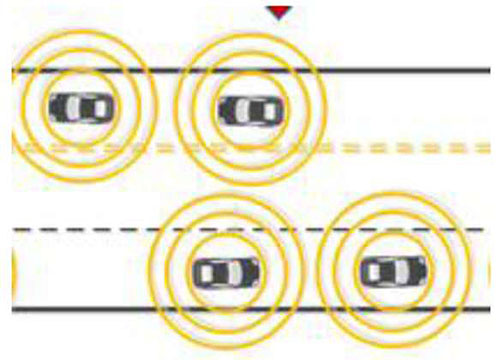
This slide contains a graphic that shows a top down view of a three-lane roadway, with two lanes moving left to right-with an arrow, and one lane moving right to left-with an arrow. All together seven cars are shown moving and an arrow from the bullet list indicates them as "nodes." All moving cars are considered "nodes" in an ad-hoc wireless network.)
Slide 13:
Basic Safety Message (BSM) Application

- Application-based short data packet
- Communicated to other vehicles 10 times per sec. or less
- Creates 360 degree awareness of surrounding
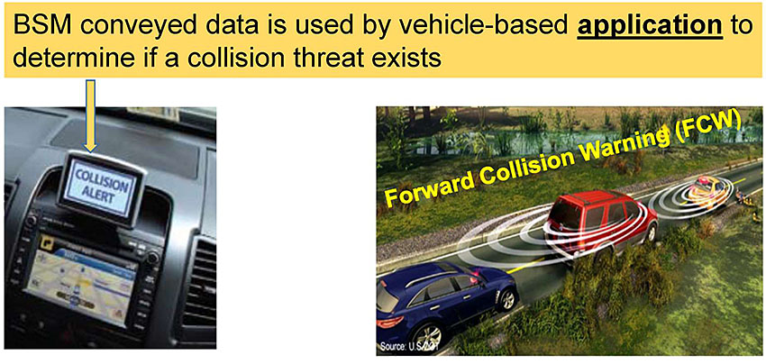
(Extended Text Description: The slide shows two photos below the top bullets. One on right shows three moving CVs in forward direction to indicate FCW (Forward Collision Warning) application. First car in the platoon slows or brakes, generates a warning message, which is displayed in the dashboard of the car in the photo on the left. An arrow from top shows a display "Collision Alert." Above the photos is the text highlighted in yellow with the text. BSM conveyed data is used by vehicle-based application to determine if a collision threat exists, with an arrow pointing to the display of the photo on the left.)
Slide 14:
Illustrate V2V Warning Messages for Drivers
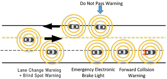
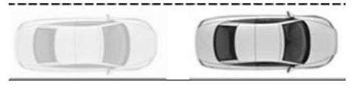
(Extended Text Description: This slide contains a graphic that shows a top down view of a three-lane roadway, with two lanes moving left to right, and one lane moving right to left. This is an animated slide. First, the text "Do Not Pass Warning" appears above the roadway along with the depiction of two connected vehicles traveling from right left (in the only lane in that direction), and one connected vehicle traveling in the opposite direction in the inside lane. An arrow indicates the direction of travel for each lane.
Second, the text "Lane Change Warning + Blind Spot Warning" appears below the roadway on the left. and another connected vehicle is depicted traveling from left to right in the outside lane, slightly ahead of the connected vehicle in the inside lane, so that the inside vehicle is in the outside vehicle's blind spot.
Third, the text "Forward Collision Warning" appears below the roadway on the right along with two connected vehicles traveling left to right in the right lane, one immediately behind the other. The lead vehicle has its brake lights on.
Fourth, the text "Emergency Electronic Brake Light" appears below the roadway in the middle along with a third connected vehicle in the right lane just behind the two vehicles associated with the Forward Collision Warning application.)
Slide 15:
Demonstration: V2P
Slide 16:
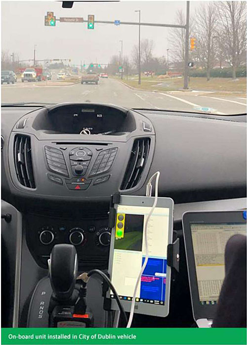
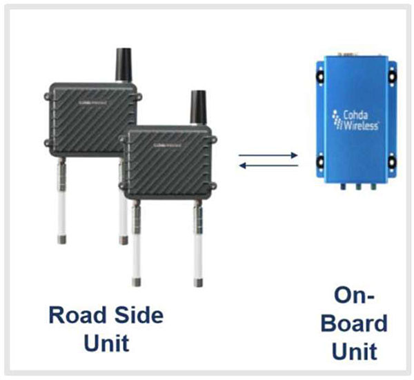
Operational Device: On-Board Unit (OBU)
- Device transmits/receives messages (data) from other devices in the vicinity
- Application process data and determine if a threat exists; issues a warning/alert to driver
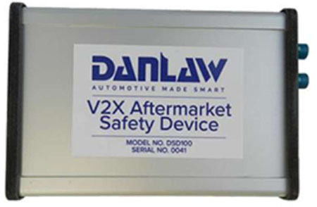
Danlaw V2X ASD being installed in the participant vehicles of the NYCDOT CV Pilot
Slide 17:
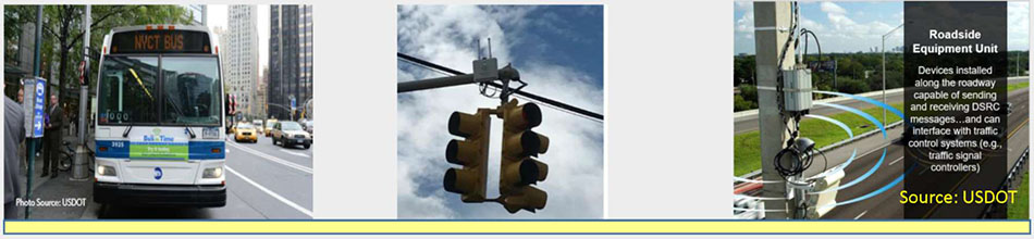
Operational Device: Roadside UNIT (RSU)
- Transmits/receives messages from OBUs
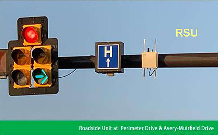
Source: City of Dublin, OH
Slide 18:
Operational Device: Roadside Equipment (RSE)
- Intersection level traffic controller processing equipment, includes RSU, and backhaul connectivity to Traffic Management Center (TMC)
Slide 19:
Transit CV Environment
What Transit Managers should Know about CV
- New class of safer-smarter transit vehicles have arrived…
- V2V will open the gates for V2X: V2I, V2P- all transit customers
OEM
Original Equipment Manufacturer
ASD
Aftermarket Safety Devices e.g. NYC 8000 vehicles
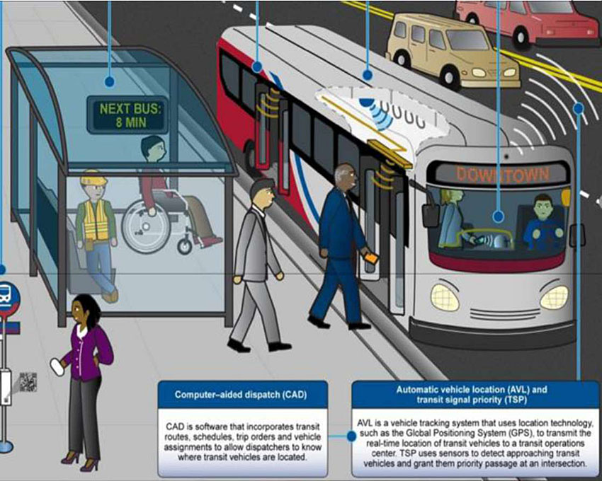
(Extended Text Description: Author's relevant notes: An example illustration of a bus stop is shown on the right side, with a sign showing next bus in 8 minutes. Two persons are walking into the bus and some are seating-standing at the bus stop. The bus is within the operational environment. Key Message is: what is it that transit managers need to learn more about the connected vehicle environment? The connected vehicle environment will be part of a transportation system that transit managers will have to face and understand. With transportation connectivity, a new class of vehicles will arrive on highways and streets that the transportation managers own - fast moving, possibly autonomous. Additionally, emerging technologies and the proposed rulemaking for light vehicles for V2V will lead to developments that open the door to new types of connected vehicle technologies, including vehicle to infrastructure and vehicle to pedestrian technologies.)
Source: GAO
Slide 20:
Transit CV Environment
What Transit Managers should Know about CV (2)
- Customer-centric Route-specific information
- How can the CV standards help me to improve my transit service?
- How can I manage CV technology?
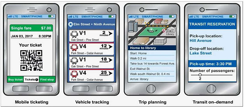
Source GAO analysis of interviews with transit providers regarding smart phone applications | GAO 16 638
Slide 21:
Transit CV Environment
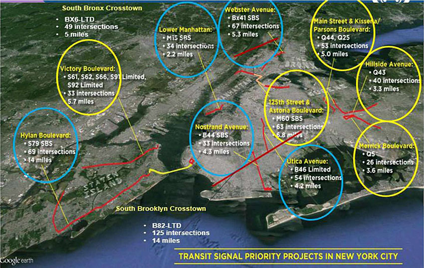
Transit Signal Priority (TSP), Chicago
With about 300 million bus trips made each year by transit riders across the Chicago region, integration of TSP technology on CTA and Pace buses will provide riders with improved on-time dependability and reduced travel times.
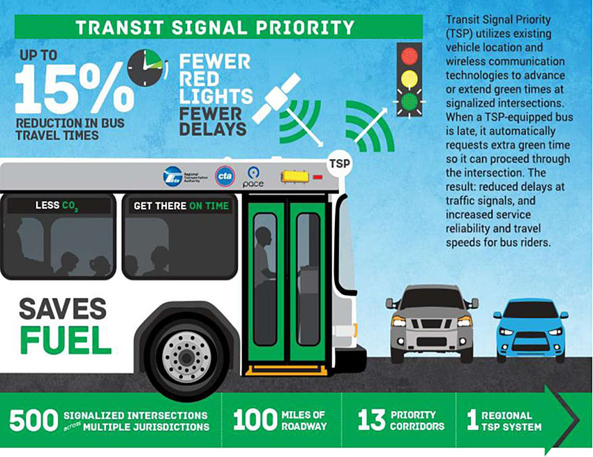
(Extended Text Description: Author's relevant notes: Transit Signal Priority is shown with a bus moving and a traffic light in front. Bus is moving while few cars are stopped at cross street. To the right on the diagram, there is a text summary: Transit Signal Priority (TSP) utilizes existing vehicle location and wireless communication technologies to advance or extend green times at signalized intersections. When a TSP-equipped bus is late, it automatically requests extra green time so it can proceed through the intersection. The result: reduced delays at traffic signals, and increased service reliability and travel speeds for bus riders.
Purpose: Convey TSP concept using Regional Transportation Authority of Northeastern Illinois (RTA) example. https://www.rtachicago.org/plans-programs/programs-and-projects/transit-signal-priority
Key Message from Author: Transit Signal Priority (TSP) utilizes existing vehicle location and wireless communication technologies to advance or extend the green light of a traffic signal to allow a CTA or Pace bus to continue through an intersection when the bus is running behind schedule—helping to reduce travel times and ensure on-time arrivals. TSP is being deployed along 13 priority corridors to help CTA (Chicago Transit Authority) and Pace buses travel along 100 miles of roadway and through about 500 intersections operated by the Illinois Department of Transportation (IDOT), the Chicago Department of Transportation (CDOT), and other local departments of transportation throughout the region. The RTA is leading this regional coordination effort, known as the Regional Transit Signal Priority Implementation Program (RTSPIP), in collaboration with the transit and highway agencies listed above.
CTA and Pace bus service is getting more reliable! Using proven technology, Chicagoland transit agencies are deploying a fully integrated Transit Signal Priority (TSP) system for bus routes on strategic corridors. With about 300 million bus trips made each year by transit riders across the Chicago region, integration of TSP technology on CTA and Pace buses will provide riders with improved on-time dependability and reduced travel times.
Who will benefit? Almost 50 percent of the region's transit riders can benefit from faster, more dependable bus service. On TSP-equipped buses, riders will see fewer traffic signal delays, enabling them to reach their destinations on time—with minimal interruption to the flow of regular traffic. In fact, traffic signal synchronization will be improved along these corridors as part of the TSP program. As bus service improves, ridership numbers are expected to grow as people see bus transit as a more attractive travel option, thus helping to reduce the region's gridlock and improving air quality.)
Source: RTA
Slide 22:
Transit CV Environment
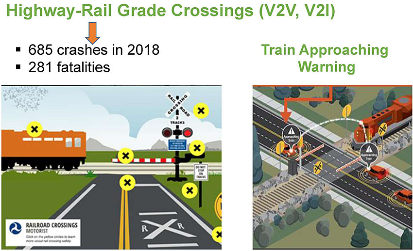
(Extended Text Description: Author's relevant notes: Two illustrations are shown about railroad grade crossing at gate. Illustration on right has a train arriving while cars are stopping. Illustration on left just shows how gates are closed with yellow X signs, a train is moving. Key Message: Example shows how an approaching train at a railroad crossing can create risks for Vehicle, and Pedestrian and avoid such a situation by showing on augmenting on-board vehicle system and projecting vehicle display time needed to wait for safe crossing. 281 fatalities in 2018 vs. in 2016). In transit environment such as this, V2I and V2V systems can effectively provide safety warnings for vehicles attempting to cross grade crossings. At time, research has not uncovered real-world case study yet. Above the left illustration are the following bullet points connected via an arrow from the text Highway-Rail Grade Crossings (V2V, V2I)\:
- 685 crashes in 2018
- 281 fatalities
Slide 23:
Slide 24:
Question
Which of the following is an incorrect statement related to CV applications?
Answer Choices
- On-Board Unit (OBU) is required for V2V communication.
- Roadside Unit (RSU) is required for V2I communication.
- ONLY Aftermarket Device (ASD) broadcasts Basic Safety Message (BSM).
- V2X includes all forms of CV communication services.
Slide 25:
Review of Answers
 a) On-Board Unit (OBU) is required for V2V communication.
Incorrect. Statement is true, OBU does transmit/receive vehicle information and is required.
b) Roadside Unit (RSU) is required for V2I communication.
Incorrect. True statement, RSU will be needed for V2I communication.
 c) ONLY ASD broadcasts Basic Safety Message (BSM).
Correct! Statement is false, functionally of both OBU and ASD are same, and can form and broadcast a BSM within the CV environment. ASD is referred by CV pilots projects for OBU.
d) V2X includes all forms of CV communication services.
Incorrect. True statement, V2X includes V2V, V2I and V2P Applies to both DSRC and C-V2X approaches.
Slide 26:
Learning Objective 2
- Identify potential communications technologies that may be used in a transit CV environment
Slide 27:
Review of Various Communications Technologies

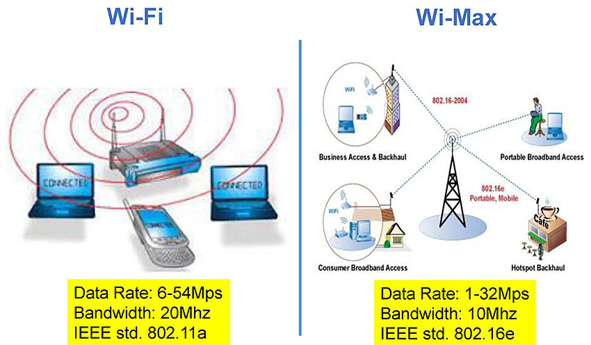
(Extended Text Description: On this slide WI-FI layout with few laptops with wireless router are shown as a cluster to the left side. To the right, WI-MAX is shown with cell tower, backhaul systems, and internet broadband wireless. Wi-Fi has the following highlighted text: Data Rate: 6-54Mps Bandwidth: 20Mhz IEEE std. 802.11a. Wi-Max has the following highlighted text: Data Rate: 1-32Mps Bandwidth: 10Mhz IEEE std. 802.16e. Author's relevant notes for this slide: Purpose: Start with broad categories, as this subject is complex survey and undergoing constant change (4G-5G). Comparison will help audience to realize broad nature of communications field.)
Slide 28:
Review of Various Communications Technologies
LTE-Long Term Evolution
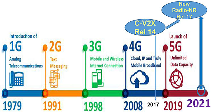
(Extended Text Description: Author's relevant notes: Slide shows LTE long term evolution chart with horizontal time frame beginning with 1G in 1979 to 5G at end 2019-2021 time frame. Purpose. 5G Updated to Release 16 expected in 2020 timeframe. Key message: What the 5G network means for wireless services? How it will support CV application: This is a topic that has occupied professionals and policy makers across industries. No clear answers yet exist in literature, but both are likely to be under discussion for a while. Note that image on top right side is projecting 5G Ecosystem across all uses, not just CV. Student Supplement details pro-cons of 5G for those seeking more information.)
Slide 29:
Review of Communications Technologies
3GPP (Third Generation Partnership Project)
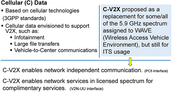
(Extended Text Description: This slide is divided into three areas. In the upper left is the text:
Cellular (C) Data
- Based on cellular technologies (3GPP standards)
-
Cellular data envisioned to support V2X, such as:
- Infotainment
- Large file transfers
- Vehicle to Center communications
To the right of the bullet points is the highlighted text: C-V2X proposed as a replacement for some/all of the 5.9 GHz spectrum assigned to WAVE (Wireless Access Vehicle Environment), but still for ITS usage.
Below that text is an arrow pointing the following text:
C-V2X enables network independent communication. (PC5 Interface)
C-V2X enables network services in licensed spectrum for complimentary services. (V2N-UU interface)
Slide 30:
Review of Communications Technologies
Competing CV Communications Alternatives
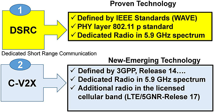
(Extended Text Description: This slide contains a diagram with the following text. On the top left a box with the text 1 - DSRC (Dedicated Short Range Communication) points to a box on the right under the text Proven Technology, which contains the following text:
✓ Defined by IEEE Standards (WAVE)
✓ PHY layer 802.11 p standard
✓ Dedicated Radio in 5.9 GHz spectrum
On the bottom there is another box with the text 2 - C-V2X which points to a box on the right under the text New-Emerging Technology, which contains the following text:
✓ Defined by 3GPP, Release 14…
✓ Dedicated Radio in 5.9 GHz spectrum
✓ Additional radio in the licensed cellular band (LTE/5GNR-Relese 17)
Slide 31:
Review of Communications Technologies
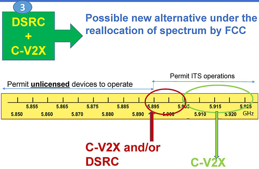
(Extended Text Description: This slide contains a Review of Communications Technologies with a box at the top with the text 3 - DSRC + C-V2X with an arrow to the text, Possible new alternative under the reallocation of spectrum by FCC. Below is a graphic depicting frequency ranges showing a range of 5.850 to 5.895 GHz which is labeled "Permit unlicensed devices to operate" and then the frequency ranges of 5.895 to 5.925 GHz labeled "Permit ITS operations." C-V2X and/or DSRC is indicated in red in the range of 5.895 to 5.905 GHz and C-V2X is indicated in green in the range of 5.905-5.925 GHz.)
Slide 32:
Review of Communications Technologies
Key Factor: Latency-a measure of time delay experienced in a system
Example: FCW application limits 0.1 sec latency
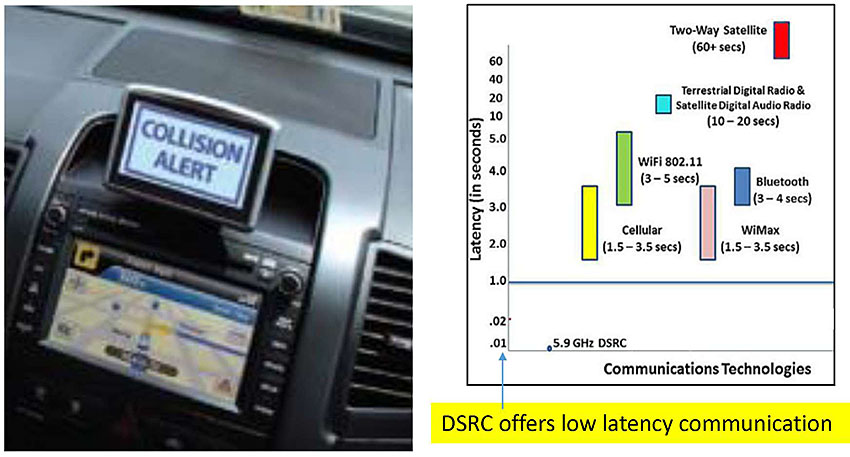
(Extended Text Description: Author's relevant notes: A photo of a car inside dashboard is shown with collision alert display. On the right, a bar chart indicates various communication technologies with latency ranges shown in text, including Cellular, WiFi, WiMax, Bluetooth, etc. DSRC has the lowest 0.1 sec latency at bottom. Purpose: Convey Latency Requirements for active safety applications, lower the latency, the faster the transmission. DSRC has low latency capability compared to cellular communication, at present.)
Slide 33:
DSRC (Dedicated Short Range Communication)
DSRC Communication Requirements
- 5.9 GHz dedicated spectrum
- IEEE 1609 Wireless Access in Vehicular Environments (WAVE) standards
- Security Credential Management System (SCMS)
- RSU and OBU (Aftermarket Safety Device-ASD)
- IEEE 802.11 for PHY layer single channel transmission
Slide 34:
DSRC
Current US Channel Assignments
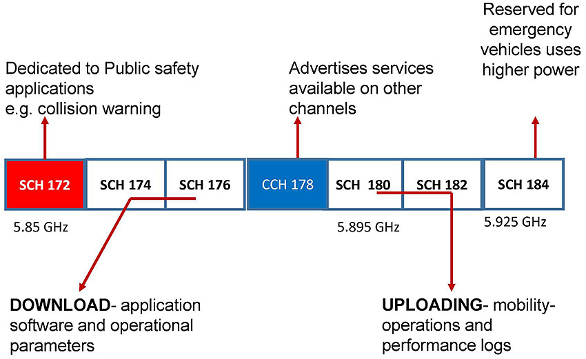
(Extended Text Description: This slide contains a series of boxes showing the current US channel assignments. Channel 172 is shown as red color box at left of slide. In the middle Channel 178 is shown in a blue text box. SCH 172 has an arrow to the text: Dedicated to Public safety applications e.g. collision warning. SCH 176 has an arrow to the text: DOWNLOAD - application software and operational parameters. CCH 178 has an arrow to the text: Advertises services available on other channels. SCH 180 has an arrow to the text: UPLOADING - mobility - operations and performance logs. SCH 184 has an arrow to the text: Reserved for emergency vehicles uses higher power.)
Slide 35:
DSRC
Channel Switching Issue: DSRC Radio Broadcasts on one channel at a time-a technology constraint
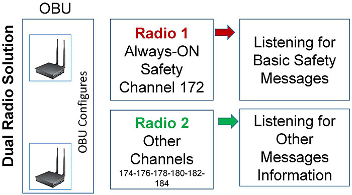
(Extended Text Description: This slide contains a simple diagram showing Channel Switching Issue: DSRC Radio Broadcasts on one channel at a time-a technology constraint. On the left of the slide, two small images of OBU are shown. A box with the text: Radio 1 - Always-ON - Safety Channel 172 points to a box with the text: Listening for Basic Safety Messages. Below those boxes is another box with the text: Radio 2 - Other Channels - 174-176-178-180-182-184, which points to a box with the text: Listening for Other Messages Information.)
Slide 36:
DSRC
Advantages
- Established, proven technology
- Tested environment sustainability
- No subscription necessary
- Low latency, higher data rate, 3-27 Mbps
Disadvantages
- Needs Government support
- Limited Spectrum-channel congestion
- Potential impacts on SCH 172
Slide 37:
DSRC
Other Potential Deployment Issues…
- Retrofitting Vehicles: Limited RSUs deployed today
- Spacing RSE at 300 meter may be a disadvantage
- Maintenance is a long-term burden
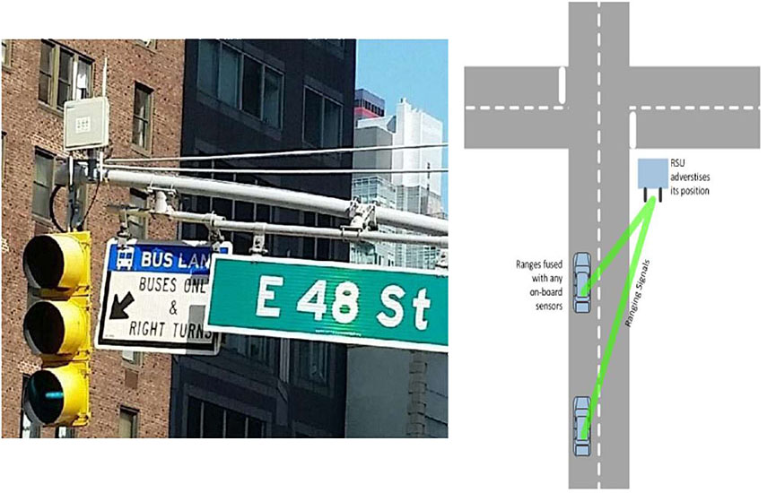
(Extended Text Description: A photo of a field location at E 48 Street depicts an RSU and a three head traffic signal. To the right is a overhead layout of an intersection graphic depicting an RSU that is advertising its position, connected via ranging signals to two vehicles heading north to the intersection, with the text, Ranges fused with any on-board sensors.)
Source: NYCDOT
Slide 38:

Slide 39:
Question
Which of the following is NOT a current attribute of DSRC?
Answer Choices
- Low latency
- No subscription required
- Widely deployed in vehicles
- Short to medium range
Slide 40:
Review of Answers
a) Low latency
Incorrect Low latency is a benefit of DSRC.
b) No subscription required
Incorrect. DSRC does not require subscription which makes it more accessible.
c) Widely deployed in vehicles
Correct! At this time, there are relatively few vehicles equipped with DSRC. US is now engaged in testing deployments. This may change in future.
d) Short to medium range
Incorrect. Short to medium range is a core characteristic of DSRC.
Slide 41:
Learning Objective 3
- Review the standards that support the transit CV environment
Slide 42:
Standards Required for Transit CV Environment
Types of Standards
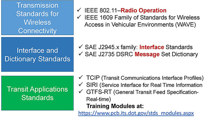
(Extended Text Description: The text boxes on left show three colored boxes from top to down, light blue, dark blue and green.
The top box contains the text: Transmission Standards for Wireless Connectivity. To the right of that box is the text:
✓ IEEE 802.11-Radio Operation
✓ IEEE 1609 Family of Standards for Wireless Access in Vehicular Environments (WAVE)
The second box contains the text: Interface and Dictionary Standards. To the right of that box is the text:
✓ SAE J2945.x family: Interface Standards
✓ SAE J2735 DSRC Message Set Dictionary
The third box contains the text: Transit Applications Standards. To the right of that box is the text:
✓ TCIP (Transit Communications Interface Profiles)
✓ SIRI (Service Interface for Real Time Information
✓ GTFS-RT (General Transit Feed Specification-Real-time)
Training Modules at: stds modules.aspx)
Slide 43:
Transmission Standards for Wireless Connectivity
IEEE 802.11 (2016)
-
Describes specification for wireless connectivity using DSRC services for:
- ASTM 2213-03 specification requirements
- Media Access Control (MAC): the message protocols that allow applications to 'connect' to the PHY layer
- PHY: the radio chips and the intervening environment in between
- IEEE 802.11 enables Ad-hoc wireless communication with IEEE 1609.x standards
Slide 44:
Transmission Standards for Wireless Connectivity
IEEE 1609 Family of Standards for Wireless Access in Vehicular Environments (WAVE) (2016)
IEEE 1609.0: Guide for Wireless Access in Vehicular Environments (WAVE) Architecture (2019)
IEEE 1609.2: Security Services for Applications and Management Messages
1609.2.1 adds SCMS (pending)
IEEE 1609.3: Network and Transport Services
IEEE 1609.4: Multi-Channel Operation Standards
IEEE 1609.12 Identifier Allocations
PCB Module CV 265 Covers IEEE 1609 WAVE Standards
Slide 45:
Interface and Data Dictionary Standards
SAE J2945.X Sets Performance Requirements
- How to use management, facilities, and security to implement a specific application, as defined by use cases
-
Performance/functional requirements:
- What, when and how often a message is sent (minimum, typical, maximum)
- Minimum quality requirements
- Security requirements
- Dialogs and data
- Requirements Traceability Matrix (RTM)
https://www.sae.org/standards/content/j2945 201712/
Slide 46:
Interface and Data Dictionary Standards
Completion of Key Interface Standards
- SAE J2945.0 Systems Engineering Guidance
-
SAE J2945/1 V2V Safety Application
- Conformance Test Specifications
- SAE J2945/2 V2V Awareness Application
- SAE J2945/9 Vulnerable Road User Application
https://www.sae.org/standards/content/j2945 201712/
Slide 47:
Interface and Data Dictionary Standards
SAE J2735 DSRC Message Set Dictionary Defines Data Structure
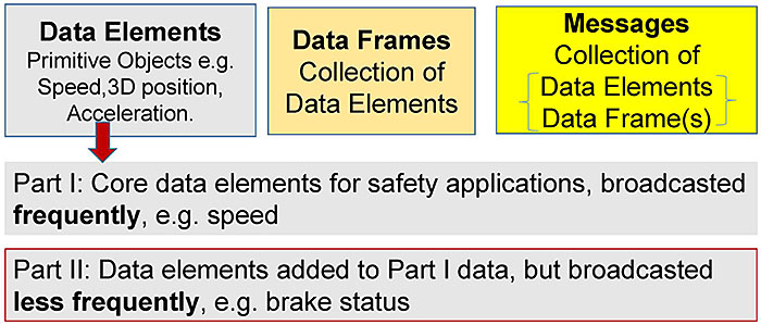
(Extended Text Description: This slide contains a series of boxes with the following text re: SAE J2735 DSRC Message Set Dictionary Defines Data Structure. There are three boxes at the top of the slide, from left to right: Data Elements - Primitive Objects e.g. Speed,3D position, Acceleration, Data Frames - Collection of Data Elements, Messages - Collection of Data Elements, Data Frame(s). An arrow from the first box connects to a box below it with the text: Part I: Core data elements for safety applications, broadcasted frequently, e.g. speed. Below that is another box, which is outlined in red, with the following text: Part II: Data elements added to Part I data, but broadcasted less frequently, e.g. brake status.)
Slide 48:
Interface and Data Dictionary Standards
SAE J2735 Messages for CV Applications
MessageFrame (FRAME)
BasicSafetyMessage (BSM)
CommonSafetyRequest (CSR)
EmergencyVehicleAlert (EVA)
IntersectionCollisionAvoidance (ICA)
MapData (MAP)
NMEAcorrections (NMEA)
PersonalSafetyMessage (PSM)
ProbeDataManagement (PDM)
ProbeVehicleData (PVD)
RoadSideAlert (RSA)
RTCMcorrections (RTCM)
SignalPhaseAndTiming Message (SPAT)
SignalRequestMessage (SRM)
SignalStatusMessage (SSM)
TravelerInformation Message (TIM)
TestMessages
Example: BasicSafetyMessage (BSM)
| Message ID | Message Type | Time Stamp | Position | Velocity | Message Check |
Slide 49:
Summary of CV Standards
Example of Safety Messages Processing
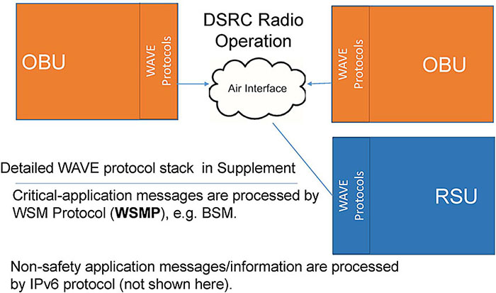
(Extended Text Description: This slide contains three connected boxes re: Example of Safety Messages Processing. On the left is a red box with OBU - Wave Protocols, on the right is a red box with OBU - Wave Protocols, both pointing to a cloud in the middle labeled DSRC Radio Operation - Air Interface. To the lower right is a blue box labeled RSU - Wave Protocols connected to the same cloud in the middle. There is also the text in the lower left quadrant, Detailed WAVE protocol stack in Supplement - Critical-application messages are processed by WSM protocol (WSMP), e.g. BSM. Non-safety applications messages/information are processed by IPv6 protocol (not shown here).)
Slide 50:

Slide 51:
Question
Which of the following is NOT a Wireless Connectivity standard?
Answer Choices
- IEEE 1609 family
- SAE J2735 data dictionary
- APTA TCIP
- IEEE 802.11
Slide 52:
Review of Answers
a) IEEE 1609 Family
Incorrect. Statement is true, we need IEEE 1609 family standards to enable wireless connectivity.
b) SAE J2735 data dictionary
Incorrect. Statement is true, J2735 is a dictionary standard that provides for the BSM.
c) APTA TCIP
Correct! The TCIP is an application oriented standard for transit and it is not required for wireless functionality.
d) IEEE 802.11
Incorrect. This standard is the baseline standard needed to deal with PHY layer medium connection in WAVE implementation.
Slide 53:
Learning Objective 4
- Describe the applications being developed in a transit CV environment
Slide 54:
Slide 55:
V2I Transit Safety Applications
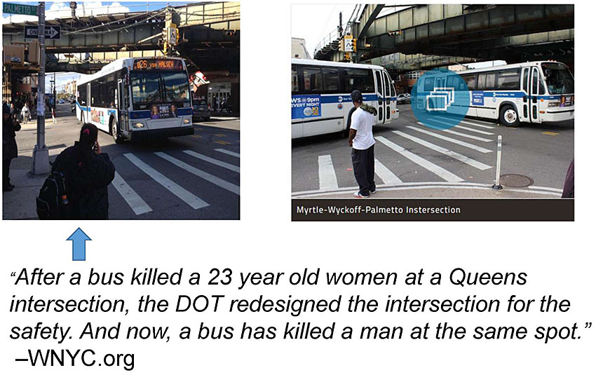
(Extended Text Description: Author's relevant notes: This slide contains two photos - photo on the left shows a bus, a man standing at the crosswalk of an intersection. Photo on the right shows two city buses and man standing in the middle of the intersection. Altogether, buses are showing how a turning situation plays out. Text underneath the photos point to the first photo, with the text: "After a bus killed a 23 year old women at a Queens intersection, the DOT redesigned the intersection for the safety. And now, a bus has killed a man at the same spot." – WNYC.org. This case study is about: a man in his 40s was struck and killed by an MTA bus early Thursday morning at an intersection in Ridgewood, Queens. The death underscores the difficulty of achieving Mayor Bill De Blasio's Vision Zero program, which seeks to eliminate traffic fatalities in New York City.)
Slide 56:
V2I Transit Safety Applications
"Edgar Torres was walking to his 6 a.m. dialysis appointment at Wyckoff Medical Center.
At 5 a.m., he reached the intersection of Myrtle Avenue, Wyckoff Avenue, and Palmetto Street. Witness Jose Velez said Torres had the light and was in the crosswalk when the crash occurred.
"He was already halfway through the intersection when the bus came turning and boom!" Velez said of the collision. "I seen the body there laying."
by Jim O'Grady wnyc.org
Slide 57:
V2I Transit Safety Applications
NYC CV Pilot Pedestrian Safety Applications
- VTRW (Vehicle Turning Right in Front of Bus)
- PCW (Pedestrian in Crosswalk Warning)
1500 MTA Transit Buses-Heavily Traveled Routes
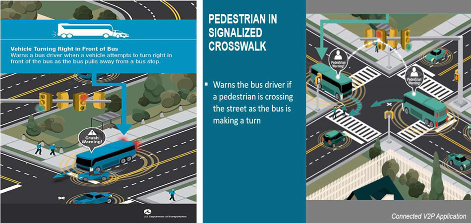
(Extended Text Description: Author's relevant notes: this slide contains an illustration at the bottom about how pedestrians are affected in the crosswalk by the movement of buses. The illustration on the left contains the text: Vehicle Turning Right in Front of Bus - Warns a bus driver when a vehicle attempts to turn right in front of the bus as the bus pulls away from a bus stop. The illustration on the right contains the text: PEDESTRIAN IN SIGNALIZED CROSSWALK - Warns the bus driver if a pedestrian is crossing the street as the bus is making a turn. Purpose: Convey what can be done to improve underlying bus-pedestrian safety within transit environment. Builds on the previous slide. Key Message: Slide has two images from USDOT that show how NYC CV pilot is handling a large fleet of transit buses in developing CV applications. Real-world issue, V2P, is heavily addressed by NYC in its Vision- ZERO based CV Pilot project, transit bus and other types of vehicles (V2V) are involved at large scale. USDOT applications example shows how V2P applications can improve safety. This application is about a bus driver being warned about a pedestrian who is crossing-bus driver will manage turning action accordingly. Image on right warns bus driver of a P- Pedestrian presence (V2P) communication, image on the left demonstrates the Vehicle Turning Right in Front of a Transit Vehicle, or VTRW application. As we can see, passenger vehicle intends to make a right turn in front of the bus at the near-side stop. Because the passenger vehicle's trajectory takes it in the path of the transit vehicle, a warning is issued to the transit vehicle that there is a dangerous situation if it moves.)
Slide 58:
V2I -V2V Transit Safety Applications
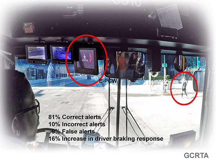
Greater Cleveland Regional Transit Authority (GCRTA)
- E-TRP (Enhanced Transit Safety Retrofit Package Project)
24 Transit Vehicles, 3 Intersections
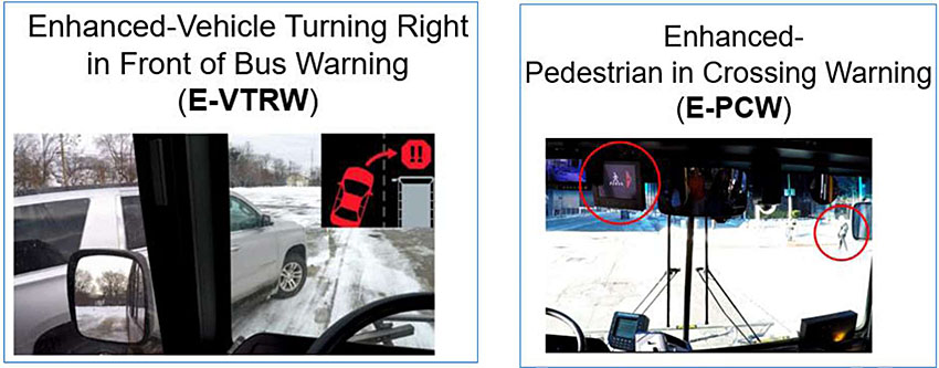
(Extended Text Description: Author's relevant notes: Two images at bottom shows turning of vehicles, first on right shows vehicles turning right in front of a bus and one after that image shows pedestrians in crosswalks. The images illustrate Enhanced-Vehicle Turning Right in Front of Bus Warning (E-VTRW) and Enhanced-Pedestrian in Crossing Warning (E-PCW). Key Message: Explains transit safety applications in Cleveland, as part of E-TRP project. Both V2I and V2I examples are shown. E stands for Enhanced. The E-TRP features enhanced versions of the Enhanced-Pedestrian in Crossing Warning (EPCW) and Enhanced Vehicle Turning Right in Front of Bus Warning (EVTRW).)
Source: Battelle Memorial Institute-USDOT
Slide 59:
Slide 60:
V2I Transit Safety Applications
Slide 61:

Slide 62:
Question
Which of the following is not a transit CV safety application?
Answer Choices
- Pedestrian turning in Front of Bus Warning (VTRW)
- Enhanced Forward Collision Warning (E-FCW)
- Highway-Rail Grade Crossing
- Transit Signal Priority (TSP)
Slide 63:
Review of Answers
a) Pedestrian turning in Front of Bus Warning (VTRW)
Incorrect. VTRW avoids a potential conflict with pedestrian movement.
b) Enhanced Forward Collision Warning (E-FCW)
Incorrect. E-FCW issue a warning alert avoiding potential V2V collision.
c) Highway Grade Crossing
Incorrect. It is a potential use case-application having impacts on collisions.
d) Transit Signal Priority (TSP)
Correct! TSP is a V2V-V2I mobility improvement application.
Slide 64:
Learning Objective 5
- Identify the challenges and approaches to the successful deployment of a transit CV environment
Slide 65:
Challenges and Approaches to the Successful Deployment of a Transit CV Environment
Key Areas of Challenges

(Extended Text Description: This slide contains a series of boxes vertically stacked on the left with the following text in each box, from top to bottom:: User Group, Transit Agency, Traffic Managers, Roadway Engineers, Maintenance Staff, Transit Vehicle Driver, Transit Passengers, and Pedestrians and Other Drivers. A bracket leads to a box with the text: What should we consider? The box points to a bullet list below:
- Institutional Framework
- Technology
- System Integration Issues
- Procurement Deployment Issues
- Security

Slide 66:
Challenges and Approaches to the Successful Deployment of a Transit CV Environment
Institutional Framework Requirements
Jurisdictional Partnerships
TRANSIT-TRAFFIC
(Extended Text Description: Author's relevant notes: Three images are shown at bottom: a bus stop and a bus, a traffic signal, and an RSU installed at roadside. Purpose: CV is multi-jurisdictional; deployments-needs a framework. Key Message: CV environment is an extension of current or planned ITS operations within multi-jurisdictions. Therefore by definition-CV deployments will need inter-agency partnerships, traffic-transit organizations, capability to connect to a TMC, bus depot, or other operational centers. For example, TSP operation is TMC-centric, but vehicles are transit types route-specific applications.)
Data Management
TMC Backhaul processing Coordinated Infrastructure Deployment: collect data, share data and interact
Slide 67:
Technology Challenges: DSRC Foundation Work
- NHTSA- ANPRM Only applies to V2V communications, V2I is not mandated
- Devices Speak the same "language"
- Understand standardized BSMs
National Highway Transportation Safety Administration (NHTSA)
Advanced Notice of Proposed Rulemaking (ANPRM)
Slide 68:
Challenges and Approaches to the Successful Deployment of a Transit CV Environment
Expertise/Training Needed to Resolve Implementation Issues
Survey Question:
What challenges did you face during implementation of the system?
Controller Area Network (CAN): information/addresses varied even across the same model of bus and required more coordination with bus manufacturers than anticipated.
Engineering challenges typical of integration work.
GCRTA E-PCW Evaluation Report
Slide 69:
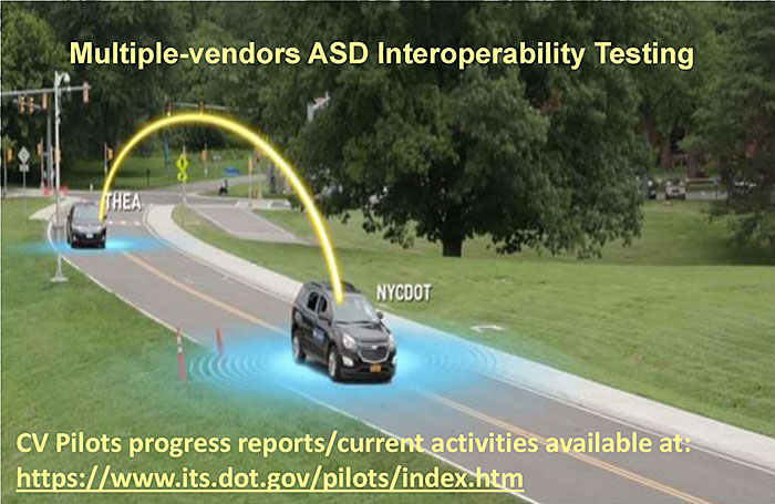
System Integration Challenge: Multiple Vendors Relationships
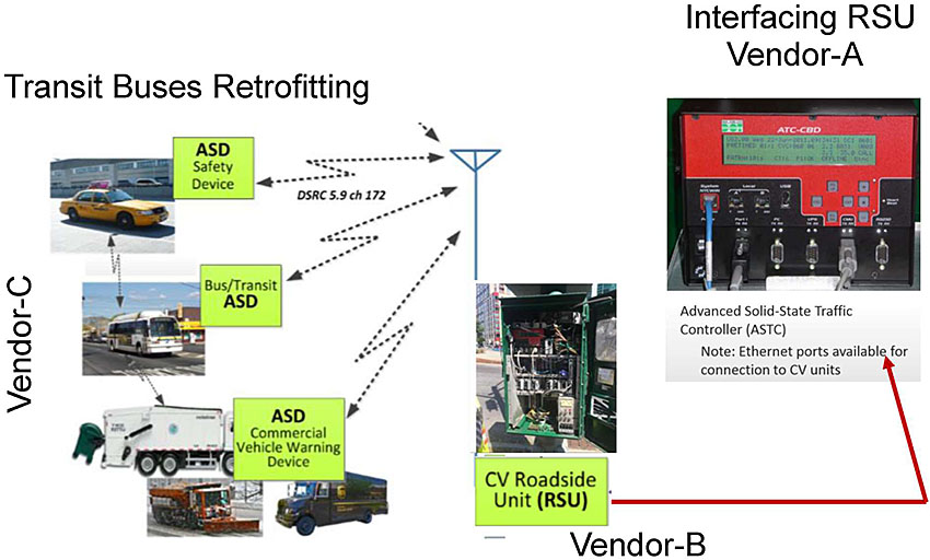
(Extended Text Description: Author's relevant notes: Photo of a traffic ATC shown at right most (Interfacing RSU Vendor-A), in the center a photo of TSU (Vendor-B), and to the left side, a series of ASD installations (Vendor-C) of taxis at top, buses below that and large trucks below buses images; all are shown with arrows from middle RSU antenna. Purpose: Many vendors are interacting in CV deployments. Transit managers are made aware what to look for. Key Message: ASD-an aftermarket automotive grade electronic device installed in a vehicle, without connection to vehicle systems, that is capable of sending and receiving the safety messages, as defined in Society of Automotive Engineers (SAE) standard J2735, Dedicated Short Range Communications (DSRC) Message Set Dictionary, version 2009-11, over a Dedicated Short Range Communication (DSRC) 5.9 GHz wireless communications link. The device has a working human-machine interface (HMI); runs V2V and V2I applications and issues audible or visual warnings and/or alerts to the driver of the vehicle in which it is installed; and has internal permanent storage capability. Multi-vendor relationships (A-B-C…) shown in the diagram are key to successful CV deployments as the technology aspects and experiences of each are different, therefore owning agency will need to be aware of issues. Example of RSU-RSE connection in Ethernet port outlet is a real-world situation that needs to be closely-coordinated for data packets transmission. Vendor resistance to providing necessary information is a known issue, and owning agency must be prepared to seek clarity from vendors to recessive and share with others the information; this is not always possible.)
Slide 70:
Deployment Challenges: Equipment Procurement
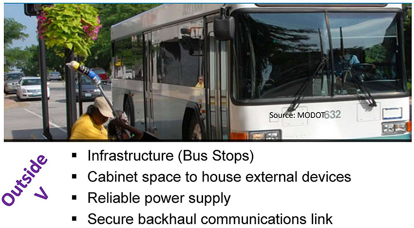
(Extended Text Description: A bus is shown at a bus stop and text discusses outside of V installations with the bullet points below:
- Infrastructure (Bus Stops)
- Cabinet space to house external devices
- Reliable power supply
- Secure backhaul communications link
Slide 71:
Deployment Challenges: Inside Vehicle Interfaces
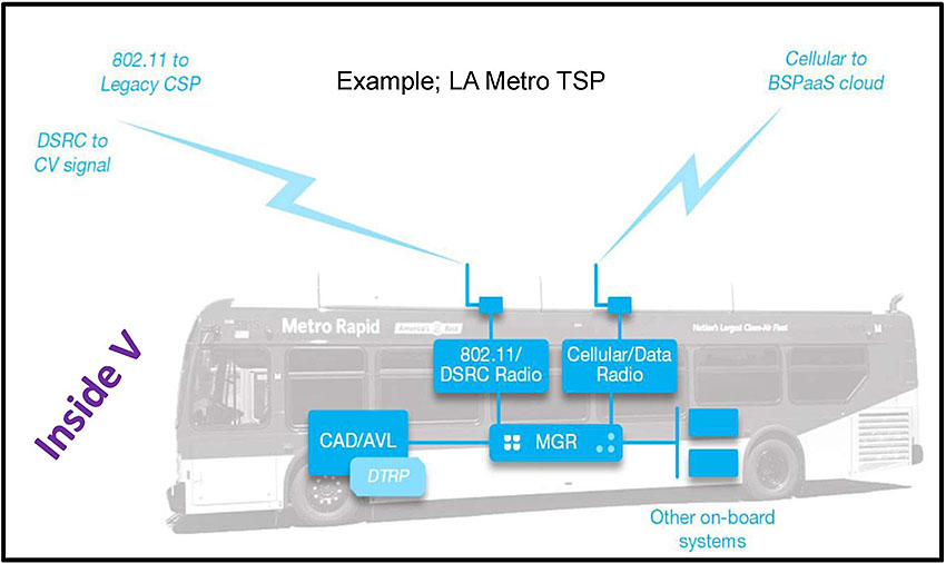
(Extended Text Description: Author's relevant notes: diagram of inside of a bus is shown with four interfaces. This is an example from LA Metro TSP. Purpose: Both V and I aspects in CV, V2V and V2I needs to be highlighted. In this slide, inside vehicle. Key Message: The slide shows four network interface operations: (1) Private radio network (2) Cellular, (3) Wi-Fi for offloading AVL information at the depot, typically 802.11 g (non-DSRC) (4) DSRC (802.11 p). Fifth one is likely to emerge in C-V2X NR operation, which is not shown in the slide.")
Source: DKS-PCB Module 24
Slide 72:
Challenges and approaches to the successful deployment of a transit CV environment
Example: MTA Transit Bus Retrofitting-Testing
- V2V communication RF (radio frequency) testing
- Through the glass antenna, roof drilling-not allowed
- Create an installation template
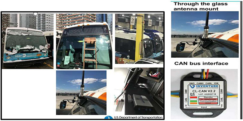
(Extended Text Description: Author's relevant notes: five images are shown in one box; all are installations activities of a bus related equipment. Another photo on right side show Bus CAN interface. Purpose: Example is needed to convey most buses will need retrofitting for ASD. Key Message: CV pilot in NYC has installed hundreds of ASDs on MTA buses. This testing template is portable to other locations.)
Slide 73:
Challenges and Approaches to the Successful Deployment of a Transit CV Environment
Standards-based Specifications
- Include Conformance Requirements for Communications media(s), standards, and security infrastructure.
-
Develop Test Plans:
- Identify how to verify conformance to the referenced standards
- Identify the system requirements
- Identify how testing will be performed, by Who?
- Consult PCB training modules: T101, T202 for detailed discussion
Slide 74:
Privacy Challenges
- Privacy between users and third parties
- Can't track a vehicle to its source and destination without appropriate authorization (for example, electronic payments)
- IEEE 1609.3 describes the use of changing MAC address at random intervals
- SAE J2945 standards address this by assigning and changing an identifier on a frequent basis
Slide 75:
Security Challenges
-
Security Credential Management System (SCMS) developed by USDOT:
- Provides the security infrastructure to issue and manage the security certificates
- Safety Message validity with SCMS to support trusted, safe/secure V2X communications and to protect driver privacy appropriately
- CV devices enroll into the SCMS, obtain security certificates and attach those certificates to their messages as part of a digital signature
- The certificates prove the device is a trusted actor
- System identifies bad actors and revoke message privileges, when necessary (IEEE 1609.2.1 pending)
Cyber security issues must be addressed in addition to the overall security needs.
More on cyber-security in Module CSE 202, under preparation.
Slide 76:
Lessons Learned
CV Device Deployment Status (as of November 2019)
| Wyoming Pilot (WYDOT) | Complete | Target |
|---|---|---|
| WYDOT Maintenance Fleet Subsystem On-Board Unit (OBU) | 32 | 90 |
| Integrated Commercial Truck Subsystem OBU | 0 | 25 |
| Retrofit Vehicle Subsystem OBU | 20 | 255 |
| WYDOT Highway Patrol | 0 | 35 |
| Total Equipped Vehicles | 52 | 405 |
| Roadside Units (RSU) along I-80 | 75 | 75 |
| Tampa Pilot (THEA) | Complete | Target |
|---|---|---|
| Vehicle Equipped with On-Board Unit (OBU) | 831 | 1080 |
| HART Transit Bus Equipped with OBU | 10 | 10 |
| TECO Line Streetcar Equipped with OBU | 8 | 8 |
| Total Equipped Vehicles | 849 | 1,100 |
| Roadside Units (RSU) at Downtown Intersections | 44 | 44 |
| New York City Pilot (NYCDOT) | Complete | Target |
|---|---|---|
| Taxi Equipped with Aftermarket Safety Device (ASD) | 1 | 3,200 |
| DCAS Fleet Equipped with ASD | 0 | 3,200 |
| MTA Fleet Equipped with ASD | 700 | 700 |
| OCME Fleet Equipped with ASD | 4 | TBD |
| NYCDOT Fleet Equipped with ASD | 639 | 700 |
| DSNY Fleet Equipped with ASD | 0 | 170 |
| Total Equipped Vehicles | 3000 | 8,000 |
| Roadside Units (RSU) at Manhattan and Brooklyn Intersections and FDR Drive | 275 | 400 |
| Vulnerable Road User (Pedestrians/Bicyclists) Device | 0 | 100 |
| PED Detection System | 9 | 10 |
![]()
Slide 77:
Lesson Learned
CV-Pilots Projects Deployments
Slide 78:
Resources for Fur mother Reading
-
CV training modules available:
- Updated: Module CV-261 (V2I)
- Updated Module CV-262 (V2V)
- CV-273 (SPaT/MAP)
- Transit Module 24 (TSP)
- CV 265 IEEE (WAVE)
- CSE 202 (Cybersecurity)
-
Additional transit applications modules are listed at:
stds modules.aspx
Slide 79:

Slide 80:
Question
Which of the following is (are) a potential barrier to implementation of transit connected vehicles?
Answer Choices
- Security
- Privacy
- Evolving standards
- All of the above
Slide 81:
Review of Answers
a) Security
Incorrect, Not the only one, but Security concerns are a potential barrier because transit agencies must trust and authenticate the information.
b) Privacy
Incorrect, Not the only one, but Privacy concerns are a potential barrier to protect a transit passenger's data from other than their intended use.
c) Evolving standards
Incorrect, Not the only one, but Evolving standards are a potential barrier because interoperability is affected.
d) All of the above
Correct! All of the above are potential barriers/issues. But know that we are currently testing CV and will soon find out!
Slide 82:
Learning Objectives
- Describe the connected vehicle (CV) environment
- Identify potential communications technologies that may be used in a transit CV environment
- Review the standards that support the transit CV environment
- Describe transit CV applications
- Identify the challenges and approaches to the successful deployment of transit CV applications
Slide 83:
Thank you for completing this module
Feedback
Please use the Feedback link below to provide us with your thoughts and comments about the value of the training.
Thank you!