Module 18: Transit and the Connected/Automated Vehicle Environment/Emerging Technologies, Applications, and Future Platforms
Student Supplement
(Note: This document has been converted from the Student Supplement to 508-compliant HTML. The formatting has been adjusted for 508 compliance, but all the original text content is included, plus additional text descriptions for the images, photos and/or diagrams have been provided below.)
Table of Contents
Module Description - 2
Introduction/Purpose - 2
Samples/Examples - 2
Reference to Other Standards - 10
Case Studies - 13
Glossary - 13
References - 14
Study Questions - 16
Icon Guide - 17
1. Module Description
"Automated vehicles open up possibilities for saving lives, saving time, and saving fuel. Automated vehicles promise to move people and goods more efficiently than we are moving them today." "Today I am announcing that the President is proposing $3.9 billion over 10 years to fund pilot projects that help accelerate the development and adoption of safe vehicle automation." - U.S. Department of Transportation Secretary Anthony Foxx, January 14, 2016
This module is a continuation of Module 11 - Transit and the Connected Vehicle Environment/Emerging Technologies, Applications, and Future Platforms. Module 11 described the connected vehicle environment using Dedicated Short Range Communications (DSRC), relevant standards, and transit applications including those in the FTA Integrated Dynamic Transit Operations (IDTO) program.
The purpose of this module is to expand discussion on the connected vehicle environment for transit to accommodate "advancing automation" in the USDOT 2015-2019 ITS strategic plan and in the recent initiative announced by the USDOT.
2. Introduction/Purpose
Module 18 will provide transit agencies and other interested participants with an overview of developments in vehicle automation that complement vehicle connectivity for both bus and rail transit. This module will define relationships between connectivity and autonomy for transit vehicle operation. It will present examples of the state-of-the art transit vehicle automation applications including autonomous lane keeping and collision avoidance warning systems. This module also will describe how connectivity and automation are being deployed in rail transit, primarily in terms of train control systems for safety and capacity.
3. Samples/Examples
Distinguishing Automated Vehicles from Connected Vehicles
Automated or autonomous?
- Automated - perform a task using machinery or computers rather than humans
- Autonomous - having the power to control oneself, make decisions
Two types of connectivity
- Connect by using Dedicated Short Range Communications technology (DSRC) for Vehicle to Vehicle (V2V) and Vehicle to Infrastructure (V2I) communications
- Connect vehicles as the Internet of Things (IoT) using commercial Wi-Fi and cellular technology
"Connected Vehicles" is a term used by the US Department of Transportation to describe a roadway environment in which wireless communications permit vehicles to communicate with other vehicles, (V2V) and with stationary devices such as traffic signals, (V2I.) Numerous benefits are posited for connected vehicles. However, connectivity does not necessarily imply that vehicles will be automated. V2V and V2I could present information to a human driver that would warn of an impending collision, but the driver would be required to act to avoid the collision.
Automated vehicles do not necessarily require wireless communications to function. Automated driving systems can use various types of sensors to acquire data about the driving environment, which is processed internally. Signals are sent from the automated driving system to the electronic components controlling vehicle steering, acceleration, and braking, to manage the driving task. Although GPS, which is a wireless communications technology, is widely used for navigation, other navigation systems such as inertial guidance, gyros, and compasses can provide location and direction to the automated driving system. Likewise, although local area wireless Internet communication is frequently used to upload software and data to an on-board automated driving system, other ways to exchange data may be used.
NHTSA Levels of Automation
In the Federal Automated Vehicles Policy released in September 2016, NHTSA changed its original five levels of automation (0 to 4) to correspond with the six levels of automation developed by SAE International which are similar to those developed by the German Federal Highway Research Institute. The six levels of automation are the following:
- At SAE Level 0, the human driver does everything.
- At SAE Level 1, an automated system on the vehicle can sometimes assist the human driver conduct some parts of the driving task; examples are anti-skid braking (ABS) and electronic traction control (ETC).
- At SAE Level 2, an automated system on the vehicle can actually conduct some parts of the driving task, while the human continues to monitor the driving environment and performs the rest of the driving task; examples are adaptive cruise control and lane-keeping assist.
- At SAE Level 3, an automated system can both actually conduct some parts of the driving task and monitor the driving environment in some instances, but the human driver must be ready to take back control when the automated system requests; Tesla Autopilot is an example.
- At SAE Level 4, an automated system can conduct the driving task and monitor the driving environment, and the human need not take back control, but the automated system can operate only in certain environments and under certain conditions; Google and Uber retrofitted vehicles are examples
- At SAE Level 5, the automated system can perform all driving tasks, under all conditions that a human driver could perform them. Google's small two-passenger car with no steering wheel, brake and accelerator pedals is an example.
Source: Federal Automated Vehicles Policy, "Accelerating the Next Revolution In Roadway Safety," September 2016, National Highway Traffic Safety Administration (NHTSA) US Department of Transportation https://www.transportation.gov/AV
Distinguishing Full Automation from Less-Than-Full Automation
NHTSA Levels 3 and 4 require the driver to take over when the system determines it no longer can accomplish the driving task. NHTSA Level 5 is defined as performing all aspects of the driving tasks under all conditions. The only human function would be to input the destination or point to which the vehicle is to navigate. Full automation permits operation of an unoccupied vehicle.
Lane Transit District Automated Docking
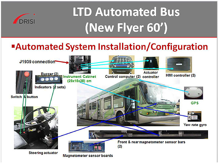
(Extended Text Description: Author's relevant notes: Lane Transit District Automated Docking - This figure shows a front and side view of a bus with arrows pointing to the locations of various equipment. The photo of the bus has photos around it showing (starting at top left): J1939 connector, instrument cabinet, control computer, actuator controller, HMI controller, GPS, Yaw rate gyro, Front and rear magnetometer bar, Magnetometer sensor boards, Steering actuator on steering wheel, Switch button, and Buzzer and indicator lights.)
Collision Avoidance, Magnitude of the Problem
| Reporting Period 2002-2014 | Reporting Period 2002-2013 | |||
|---|---|---|---|---|
| Mode | Collisions | Fatalities | Injuries | Total Casualty and Liability Expenses by Mode |
| Total Bus, Demand Responsive and Van Pool | 85,391 | 1,340 | 201,382 | $5.75 Billion |
| Total Rail | 6,118 | 1,303 | 89,806 | $3.17 Billion |
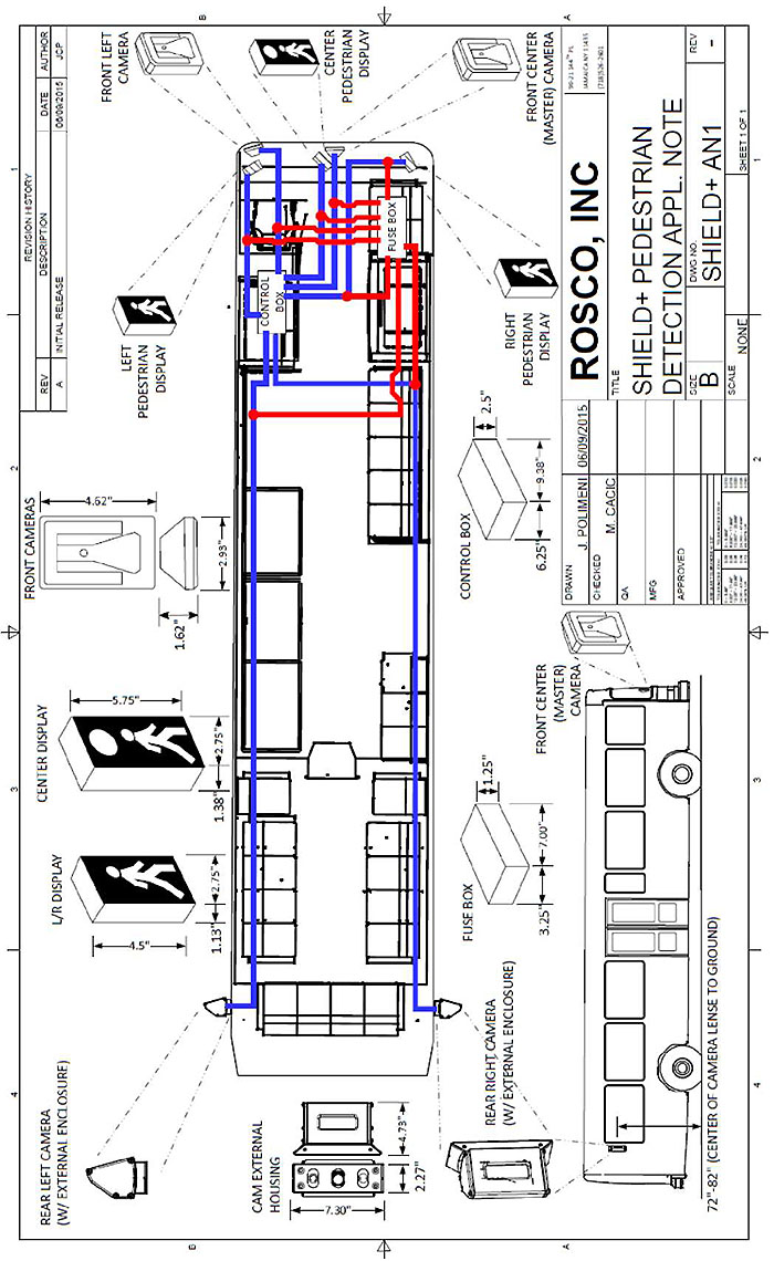
(Extended Text Description: ROSCO, Inc. Shield+ Pedestrian Detection Appl. Note - This figure shows a plan view drawing of a bus with images showing the placement of cameras and indicators for the Rosco/Mobileye Shield+ system. Red lines show the wiring for electrical connections among the components. Author's relevant notes: This diagram shows the system that was installed in each of the 38 buses in the WSTIP pilot. The Rosco/Mobileye Shield+ system includes the following components: Forward-facing center camera detects vulnerable road users (VRU's) which are pedestrians and bicyclists, reads speed limit signs, reads lane markings and measures distance to vehicles ahead of bus. Forward left camera detects pedestrians in blind area behind left front pillar when bus is turning. Rear right and left side cameras detect VRU's in blind spots behind driver. Three VRU warning displays are located in view of the driver on the left, center and right interior windshield and pillars.)
Washington State Transit Insurance Pool Safety Pilot
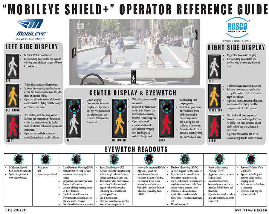
(Extended Text Description: Author's relevant notes: Mobileye Shield+ Operator Reference Guide - This figure shows a guide for bus drivers illustrating the alerts and warnings displayed by the Shield+ system. Rectangular indicators show an image of a pedestrian walking. The image is shown with no color when there is no pedestrian detected, yellow illumination when a pedestrian is detected close to the bus and red illumination when there is imminent risk of collision with the pedestrian.)
Enlargement of center panel
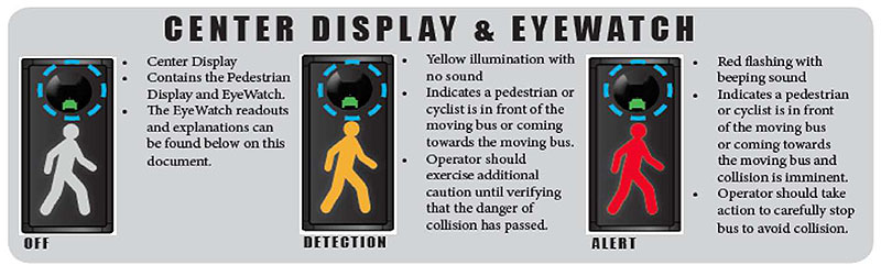
(Extended Text Description: This figure shows a close-up of the Center Display indicator which also has a circle above the pedestrian image that contains a green image representing that there is a vehicle in front of the bus. Additional bullet items contain the following text:
OFF
- Center Display
- Contains the Pedestrian Display and Eyewatch
- The Eyewatch readouts and explanations can be found below on this document.
DETECTION
- Yellow illumination with no sound
- Indicates a pedestrian or cyclist is in front of the moving bus or coming towards the moving bus.
- Operator should exercise additional caution until verifying that the danger of collision has passed.
ALERT
- Red flashing with beeping sound
- Indicates a pedestrian or cyclist is in front of the moving bus or coming towards the moving bus and collision is imminent.
- Operator should take action to carefully stop bus to avoid collision.
CItyMobil2 Demonstrations
| Demo Type | Location | Start Month | End Month | Vehicle Mfr. | # of Veh. | Route (km) | Stations Served | # of Riders |
|---|---|---|---|---|---|---|---|---|
| Lausanne, CH | 4/2015 | 8/2015 | Easymile | 4 | 1.5 | 6 | 7,000 | |
| La Rochelle, FR | 12/2014 | 4/2015 | Robosoft | 6 | 14,660 | |||
| Trikala, GR | 9/2015 | 1/2016 | Robosoft | 6 | 2.5 | 12,150 | ||
| Small Scale | Antibes, FR | 1/2016 | 3/2016 | Easymile | 4 | 1.0 | 5 | 4,000 |
| Oristano, IT | 7/2014 | 9/2014 | Robosoft | 2 | 1.3 | 7 | 2,500 | |
| Vantaa, FI | 7/2015 | 8/2015 | Easymile | 4 | 1.0 | 19,000 | ||
| San Sebastian, ES | 4/2014 | Robosoft | 3 | 3,500 | ||||
| Showcase | Bordeaux, FR | 10/2015 | 10/2015 | Easymile | 4 | 1.0 | 2 | |
| Leon, ES | 9/2014 | 9/2014 | Robosoft | 2 | ||||
| Warsaw, PO | 4/2016 |
EZ10 Vehicle Features
The EZ10 is manufactured by French light weight automobile maker Ligier. Founded in 1971 and with a background in motor racing (including 20 years in Formula 1), Ligier is the second largest European microcar provider. Ligier marketed electric vehicles since 2008.
EZ10 is an electric people mover. It can transport up to 12 people six seating positions and six standing positions) and can cater to reduced mobility passengers.
The shuttle has no steering wheel and neither dedicated front nor back. At any point on its route EZ10 can easily change its direction without needing a short turn. Source: https://easymile.com/mobility-solution
CityMobil2 - Easymile EZ10 Vehicle Specifications
Capacity: 12 persons (6 seating and 6 standing)
Cruising speed: 20 km/h (12 mph) Maximum speed: 40 km/k (25 mph)
Propulsion engine: Electric asynchronous
Autonomy: up to 14 hours of operation
Battery: Lithium-ion (LiFeP04
Battery Charger: 110V - 230V 16A
Length: 3,928 m / 154.6"
Width: 1,986 m / 78.2"
Height: 2,750 m / 108.3"
Wheelbase: 2,800 m / 110.2"
Payload: 1700 kg / 771 lbs Fully loaded: 2800 kg / 1,270 lbs
Robosoft RobuCITY Vehicle Specifications
Capacity: 10persons (6 seating and 4 standing)
Maximum speed: 32 km/h
Propulsion engine: 7.5 KW DC 72V
Range: 20-30 km
Battery: Lead acid 6 V 225Ah
Battery Charger: 110V - 230V 25A
Length: 5,000 mm/196.8"
Width: 1,986 mm/78.1"
Height: 2,670 mm/105.2"
http://www.robosoft.com/products/- content is no longer available.
Click the following link to see the YouTube video of the Trikala demonstration that shows operation of low speed transit in mixed pedestrian and auto traffic at night. https://www.youtube.com/watch?v=pLsmsTj393o
Positive Train Control
What is Positive Train Control?
"Positive Train Control" (PTC) describes technologies designed to automatically stop a train before certain accidents caused by human error occur. Specifically, PTC as mandated by Congress must be designed to prevent:
- Train-to-train collisions
- Derailments caused by excessive speed
- Unauthorized incursions by trains onto sections of track where maintenance activities are taking place
- The movement of a train through a track switch left in the wrong position
The Rail Safety Improvement Act of 2008 (RSIA) requires passenger railroads and Class I freight railroads to install PTC by the end of 2015 on main lines used to transport passengers or toxic-by-inhalation (TIH) materials.
The PTC systems that will be installed to meet the statutory mandate are overlay systems, meaning they supplement, rather than replace existing train control systems.
4. Reference to Other Standards
ASCE Standard 21-13 Automated People Movers is a consolidation of previous four-part Automated People Mover Standards. An Automated People Mover (APM) is defined as a guided transit mode with fully automated operation, featuring vehicles that operate on guideways with exclusive right-of-way. Chapters: 1-11 cover requirements for design of an APM system, and Chapters 12-16 cover requirements for an APM in passenger operation, including chapters on security; emergency preparedness; system verification and demonstration; operations, maintenance, and training; and operational monitoring. Source: ASCE
IEEE SCC42 Transportation (IEEE Standards Coordinating Committee on Transportation)
Leads the coordination of IEEE standardization activities for technologies related to transportation, especially in the areas of connected vehicles, autonomous/automated vehicles, inter- and intra-vehicle communications, and other types of transportation electrification. These technologies include but are not limited to Mobile Apps, Sensor Networks, and Communications that allow human to vehicle, vehicle to vehicle, vehicle to infrastructure, vehicle to platform, and vehicle to everything exchange of information and data. Where standardization needs exist, the SCC will develop guides, recommended practices, standards, and common definitions of terms.
IEEE P2040 - Standard for Connected, Automated, and Intelligent Vehicles: Overview and Architecture - This standard defines an architectural framework for connected, automated and intelligent vehicles. This standard leverages existing applicable standards.
IEEE P2040.1 - Standard for Connected, Automated and Intelligent Vehicles: Taxonomy and Definitions - This standard specifies the taxonomy and definitions for connected, automated, and intelligent vehicles.
IEEE P2040.2 - Standard for Connected, Automated, and Intelligent Vehicles: Testing and Verification - This standard defines an overarching framework of testing and verification of the connectivity, automation, and intelligence aspects and their combination for connected, automated and intelligent vehicles. This standard identifies existing applicable standards for testing and verification, and defines the integration of these standards into a consistent testing environment.
ISO 19091 Intelligent Transport Systems -- Cooperative ITS -- Using V2I and I2V communications for applications related to signalized intersections
This document describes the use cases, information needs, requirements, data frames, and data elements for several applications that address safety, mobility, and ecological sustainability.
SAE J3018 Guidelines for Safe On-Road Testing of SAE Level 3, 4, and 5 Prototype Automated Driving Systems (ADS) Scope: This document provides guidelines for the safe conduct of on-road tests of vehicles equipped with prototype conditional, high, and full (levels 3-5) automated driving systems (ADSs), as defined by SAE J3016. It does not include guidance for testing production ADSs intended for sale to the general public. The scope is further limited to testing of automated prototype vehicles on public roads. These guidelines do not address: � Testing of driver assist (Level 1) or partial (Level 2) automation systems, which rely on a human driver to monitor the environment. (See SAE J3016 for Definitions of Levels of Automated Systems.) � Closed-course testing. � Component-level testing. The precise regime of road testing for a particular prototype will depend on the intended level of automation and the targeted capabilities of the prototype (see SAE J3016 for more information). A prototype suitable for testing on public roadways is presumed to have already passed laboratory and/or closed-course testing, which are not addressed by this document.
SAE 3092 Dynamic Test Procedures for Verification & Validation of Automatic Driving Systems (ADS) This document provides dynamic test procedure information and guidelines for verification and validation (V&V) of automated driving systems (ADSs). The levels of automation addressed in this document include conditional (level 3), high (level 4), and full (level 5) as defined by SAE J3016; when activated, these ADSs do not rely on a human driver for monitoring and responding to the vehicle or traffic environment.
SAE J3131 Automated Driving Reference Architecture SAE J3131 defines an automated driving reference architecture that contains functional modules supporting future application interfaces for Levels 3 through 5 (J3016). The architecture will model scenario-driven functional and nonfunctional requirements, automated driving applications, functional decomposition of an automated driving system, and relevant functional domains (i.e., functional groupings). Domains include, but are not limited to, automated driving (i.e., automation replacing the human driver), by-wire and active safety, and those related to automated recovery from faults and system failures (e.g., system bringing the vehicle to a safe state). The architecture will address Tier 1 and Tier 2 functional groupings. The document will include one example instantiation being divides the functionality into two functionality groupings, and will detail the functional and information interface between the groups.
Federal Railroad Administrations Regulations for Positive Train Control Subpart I�Positive Train Control Systems
Sec.
236.1001 Purpose and scope.
236.1003 Definitions.
236.1005 Requirements for Positive Train Control systems.
236.1006 Equipping locomotives operating in PTC territory.
236.1007 Additional requirements for high speed service.
236.1009 Procedural requirements.
236.1011 PTC Implementation Plan content requirements.
236.1013 PTC Development Plan and Notice of Product Intent content requirements and Type Approval.
236.1015 PTC Safety Plan content requirements and PTC System Certification.
236.1017 Independent third party Verification and Validation.
236.1019 Main line track exceptions.
236.1021 Discontinuances, material modifications, and amendments.
236.1023 Errors and malfunctions.
236.1025 [Reserved] IflHIl
236.1027 PTC system exclusions.
236.1029 PTC system use and en route failures.
236.1031 Previously approved PTC systems.
236.1033 Communications and security requirements.
236.1035 Field testing requirements.
236.1037 Records retention.
236.1039 Operations and Maintenance Manual.
236.1041 Training and qualification program, general.
236.1043 Task analysis and basic requirements.
236.1045 Training specific to office control personnel.
236.1047 Training specific to locomotive engineers and other operating personnel.
236.1049 Training.
Association of American Railroads (AAR) Standards for PTC - Manual of Standards and Recommended Practices Section K
Part I - Railway Electronics System Architecture and Concepts of Operations (9000 Series)
Part II - Locomotive Electronics and Train Consist System Architecture (9100 Series)
Part III - Wayside Electronics and Mobile Worker Communications (9200 Series)
Part IV - Office Architecture and Railroad Electronics Messaging (9300 Series)
Part V - Electronics Environmental Requirements and System Management (9400 Series)
Part VI - Railway Data Management and Communications (9500 Series)
Communications Based Train Control Standards
CBTC signaling is currently standardized in accordance with IEEE 1474.1 and has become the reference technology for metro operators worldwide.
IEEE defines CBTC as a continuous automatic train control system utilizing
- High-resolution train location determination, independent of track circuits
- Continuous, high-capacity, two-way train-to-trackside data communications
- Train borne and trackside processors capable of performing essential functions
1474.1- 2004 IEEE Standard for Communications-Based Train Control (CBTC) Performance and Functional Requirements
1474.2- 2003 IEEE Standard for User Interface Requirements in Communications-Based Train Control (CBTC) Systems
1474.3- 2008 IEEE Recommended Practice for Communications-Based Train Control (CBTC) System Design and Functional Allocations
1474.4-2011 IEEE Recommended Practice for Functional Testing of a Communications-Based Train Control (CBTC) System
Source: Eric Louis-Marie and Dr. Peter Nuechter, "CBTC Connectivity Solutions White paper Edition 2011," Huber+Suhner AG
https://literature.hubersuhner.com/Marketsegments/Transportation/RailCBTCEN/
5. Case Studies
Case Studies shown in the presentation are:
- Minnesota Bus on Shoulders - Automated Guidance for Buses Operating on Narrow Freeway Shoulders
- Lane Transit District BRT Automated Docking - Using Automated Bus Guidance for BRT Operations
- Washington State Transit Insurance Pool Safety Pilot - Testing Automated Collision Avoidance Warning Systems for Buses
- CItyMobil2 Demonstrations - Testing Low-Speed Automated Road Transit in Europe
- Communications Based Train Control (CBTC) - Implementing CBTC at New York City Transit
6. Glossary
| Term | Definition |
|---|---|
| Automated Vehicles (AV) | Vehicles that use computers or machinery to accomplish some portions of the driving task instead of a human driver |
| Autonomous Emergency Braking (AEB) | Braking that is initiated and accomplished by a computer system rather than a human driver |
| Bus Rapid Transit (BRT) | A bus transit system that operates on exclusive lanes or roadways |
| Collision Avoidance System (CAS) | Computer system that warns a driver of an impending or potential collision and can trigger an AEB system if present |
| Communications Based Train Control (CBTC) | A train signaling and control technology that uses a communications architecture to create a virtual separation zone around a train. That zone can be adjusted to allow for changes in speed, frequency of trains, and train length. |
| Connected Vehicles (CV) | A roadway environment in which wireless communications permit vehicles to communicate with other vehicles, (V2V) and with stationary devices such as traffic signals, (V2I.) |
| Connected/Automated Vehicles (CAV) | Vehicles that use computers or machinery to accomplish some portions of the driving task instead of a human driver and communicate wirelessly with other vehicles and stationary devices |
| Platooning | A column of vehicles operating in coordination |
| Positive Train Control (PTC) | Railroad signaling and control technologies mandated by the US Congress designed to automatically stop a train before certain accidents caused by human error occur |
| Telematics | Long distance transmission of computerized information |
7. References
- J. M. Lutin, A. L. Kornhauser, E. Lam, "The Revolutionary Development of Self-Driving Vehicles and Implications for the Transportation Engineering Profession," ITE Journal, Vol. 83, Number 7, Institute of Transportation Engineers, Washington, D.C., July 2013, pp. 28-32
- Patrick Chan, "Module 11: Transit and the Connected Vehicle Environment/Emerging Technologies, Applications, and Future Platforms," ITS Transit Standards Professional Capacity Building Program, US Department of Transportation, 2015, StandardsTraining/Modules.aspx?Year1Transit=1&ModuleID=66#mod66
- "Connected Vehicles 101" online course http://www.citeconsortium.org/course/connected-vehicles-101/- content is no longer available.
- "Connected Vehicles 102" online course https://www.its.dot.gov/pcb/documents/Connected Vehicles 102.pdf- content is no longer available.
- Jim Barbaresso, Gustave Cordahi, Dominie Garcia, Christopher Hill, Alex Jendzejec, Karissa Wright, "USDOT's Intelligent Transportation Systems (ITS) ITS Strategic Plan 2015-2019," Booz Allen Hamilton, for US Department of Transportation Intelligent Transportation Systems, Joint Program Office, May 15, 2014 http://www.its.dot.gov/strategicplan- content is no longer available.
- "Levels of Road Vehicle Automation," SAE International http://articles.sae.org/13573/
- National Highway Traffic Safety Administration, "Preliminary Statement of Policy Concerning Automated Vehicles," U.S. Department of Transportation, Washington, D.C., May 30, 2013, http://www.nhtsa.gov/About+NHTSA/Press+Releases/U.S.+Department+of+Transportation+Releases+Policy+on+Automated+Vehicle+Development- content is no longer available. Accessed June 20, 2013
- Federal Automated Vehicles Policy, "Accelerating the Next Revolution In Roadway Safety," September 2016, National Highway Traffic Safety Administration (NHTSA) US Department of Transportation https://www.transportation.gov/AV accessed September 24, 2016
- Bryant Walker Smith, "SAE Levels of Driving Automation," The Center for Internet and Society, December 18, 2013, https://cyberlaw.stanford.edu/blog/2013/12/sae-levels-driving-automation accessed July 25, 2014
- "Intelligent Transportation Systems Vehicle-to-Infrastructure Technologies Expected to Offer Benefits, but Deployment Challenges Exist," Government Accountability Office (GAO) Report to Congressional Requesters, September 2015, http://gao.gov/products/GAO-15-775
- Craig Shankwitz, "Minnesota Bus on Shoulder System (BoSS)," Automating Public Mass Transit in the Connected and Automated Era, Presentation at the Transportation Research Board Annual Meeting, 13 January 2015
- Greg Larson, "Vehicle Assist and Automation (VAA) Using Bus Steering Automation Technology to Improve Safety, Costs, and Efficiency," Caltrans Division of Research, Innovation and System Information (DRISI), Power Point Presentation for CalACT Spring Conference
- "Field Operational Tests of Vehicle Assist and Automation Technologies California-Oregon VAA Team," Ching-Yao Chan and Wei-Bin Zhang 5th National BRT Conference Las Vegas August 22, 2012
- "Demo '97: Proving Ahs Works," Federal Highway Administration, Public Roads Vol. 61 No. 1 Date: July/August 1997, https://www.fhwa.dot.gov/publications/publicroads/97july/demo97.cfm
- Special Investigation Report - "The Use of Forward Collision Avoidance Systems to Prevent and Mitigate Rear End Crashes," National Transportation Safety Board (NTSB), May 19, 2015 http://www.ntsb.gov/safety/safety-studies/Documents/SIR1501.pdf
- J. M. Lutin, A. L. Kornhauser, J. Spears, L. F. Sanders, "A Research Roadmap for Substantially Improving Safety for Transit Buses through Autonomous Braking Assistance for Operators," Paper 16-1246, Compendium of Papers, Transportation Research Board Annual Conference, January 2016
- "Collision Avoidance with Pedestrian Side-Sensing," Mobileye/Rosco Vision Systems, brochure
- CityMobil2, "Cities Demonstrating Automated Road Passenger Transport," web site, accessed November 12, 2015 http://www.citymobil2.eu/en/
- EasyMile Ez10 Vehicle Specifications: https://easymile.com/mobility-solution- content is no longer available.
- Robosoft RoboCITY Vehicle Specifications; http://www.robosoft.com/products/- content is no longer available.
- "$205.8M in Contracts Approved to Install Communications-Based Train Control System," MTA News, Monday, July 20, 2015 - 13:24 https://www.mta.info/news-cbtc-new-york-city-transit-subway-l-7/2015/07/20/2058m-contracts-approved-install
- Eric Louis-Marie and Dr. Peter Nuechter, "CBTC Connectivity Solutions White paper Edition 2011," Huber+Suhner AG https://literature.hubersuhner.com/Marketsegments/Transportation/RailCBTCEN/
- The Joint Council on Transit Wireless Communications, "Positive Train Control White Paper - May 2012"
- "Positive Train Control, AAR" https://www.aar.org/search/Pages/results.aspx?k=Positive%20Train%20Control- content is no longer available.
- "Collision of Metrolink Train 111 With Union Pacific Train LOF65-12 Chatsworth, California September 12, 2008," Accident Report, National Transportation Safety Board NTSB/RAR-10/01 PB2010-916301 Notation 8175, Adopted January 21, 2010, http://www.ntsb.gov/investigations/AccidentReports/Reports/RAR1001.pdf- content is no longer available.
- 49 CFR Part 229, 234, 235, et. al: Positive Train Control Systems; Final Rule, Federal Railroad Administration, January 15, 2010, https://railroads.dot.gov/elibrary/49-cfr-part-229-234-235-et-al-positive-train-control-systems-final-rule
- Association of American Railroads, Safety and Operations, "Manual of Standards and Recommended Practices Section A, Part I," 2/26/2016
8. Study Questions
1. In a NHTSA Level 3 automated vehicle, the driver is:
- expected to be available for control in certain areas
- not expected to be available for control during the trip
- responsible for monitoring and available to resume control
- in complete and sole control
2. Which of the following bus pilot technologies is most reliant on connected vehicle (V2V) technology?
- Automated Docking
- Bus on Shoulder
- Hybrid Propulsion
- Bus Platooning
3. Which of the following statements is true?
- Casualty and liability expenses for rail transit far exceed those for bus transit
- Driver reaction time is not a factor in avoiding bus collisions
- National Transportation Safety Board does not require forward collision warning systems on all new vehicles
- Transit buses are currently being delivered with Autonomous Emergency Braking
4. Which of the following was not true of the Citymobil2 demonstrations?
- The program was funded at about $19.5 million by the European Union
- Two different contractors each built six robotic vehicles
- The vehicles traveled at low speed and carried passengers
- The vehicles required exclusive rights-of-way with no pedestrian or vehicular crossings
5. Which of the following statements is true?
- Positive Train Control standards are voluntary
- All Communications Based Train Control Systems must be interoperable
- Communications Based Train Control Systems allow only one train in a fixed block at a time
- Positive Train Control systems and Communications Based Train Control systems can be overlaid on existing fixed block signal systems
9. Icon Guide
The following icons are used throughout the module to visually indicate the corresponding learning concept listed out below, and/or to highlight a specific point in the training material.
1) Background information: General knowledge that is available elsewhere and is outside the module being presented. This will be used primarily in the beginning of slide set when reviewing information readers are expected to already know.

2) Tools/Applications: An industry-specific item a person would use to accomplish a specific task, and applying that tool to fit your need.
Example: Systems engineering, specifications, test documentation, etc. A systems engineering approach to developing an ATC procurement specification.

3) Remember: Used when referencing something already discussed in the module that is necessary to recount.

4) Refer to Student Supplement: Items or information that are further explained/detailed in the Student Supplement.