Transit Module 23: Leveraging Communications Technologies for Transit On-board Integration
HTML of the Student Supplement
(Note: This document has been converted from the Student Supplement to 508-compliant HTML. The formatting has been adjusted for 508 compliance, but all the original text content is included, plus additional text descriptions for the images, photos and/or diagrams have been provided below.)
Module 23: Leveraging Communications Technologies for Transit On-board Integration
Table of Contents
Introduction/Purpose - 2
Samples/Examples - 2
Reference to Other Standards - 19
Case Studies - 23
Glossary - 23
References - 25
Study Questions - 26
Module Description
There are a wide variety of onboard transit technologies and they are integrated using several types of communications technologies. These onboard technologies facilitate and automate operations, management, maintenance, traveler information, safety, and security functions of public transit systems. With the advent of newer communication technologies, onboard technologies can be integrated via an onboard transit architecture that is comprised of on-board devices, communications pathways (on and to/from the vehicle), functionality, and interfaces to the vehicle. Onboard devices include a mobile data terminal (MDT), vehicle logic unit (VLU) (sometimes combined with an MDT), equipment to support supervisory and support functions (e.g., ruggedized laptop), Automated Vehicle Announcement (AVA) System (covered in Modules 6 and 7), Automatic Passenger Counter (APC) System (covered in Modules 2 and 5), an Event Data Recorder System (EDRS) and Vehicle Component Monitoring (VCM) (covered in Modules 2 and 5), and Onboard Video Surveillance System (covered in Modules 2 and 5). Module 19 provides details of how to use onboard hardware and software standards and provides case studies and examples that demonstrate how to procure systems that use these standards.
1. Introduction/Purpose
This module provides details on how to leverage current communication technologies to integrate onboard devices and provides case studies and examples that demonstrate the use of these technologies. The information in this module will help participants further understand those communication technologies that support the integration of onboard transit devices for buses, specifically Internet of Things (IoT) Gateways, Mobile Gateway Router (MGR), future second generation onboard architectures and the evolution of onboard IoT edge logic. Topics that will be covered in this module include current and future on-board architectures, IoT gateways, moving onboard functionality to the cloud, and transit agency considerations.
2. Samples/Examples
2.1. Los Angeles County Metropolitan Transportation Authority (LA Metro) Transit Signal Priority (TSP) Concepts
LA Metro conducted a TSP concept development activity that resulted in the following:
- Vehicle-to-Infrastructure (V2I) Connected Vehicle (see Figure 1)
- Vehicle-to-Infrastructure (V2I) Cellular to Isolated Signal (see Figure 2)
- Vehicle-to-Center (V2C) Cellular to Centralized TMC (see Figure 3)
- Center-to-Center (C2C) Fully Centralized TOC and TMC (see Figure 4)
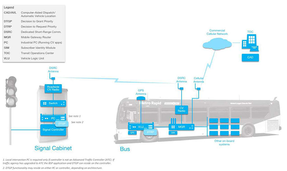
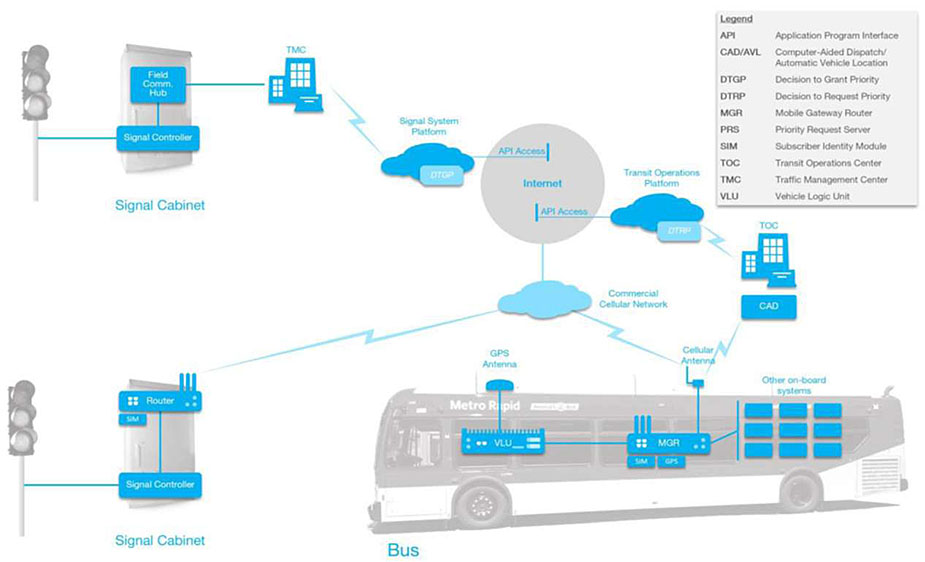
(Extended Text Description: Figure 1. V2I Connected Vehicle Concept has a graphic showing an LA Metro, Metro Rapid bus in the lower right-hand side of the figure, a signal cabinet in the lower left-hand side of the slide, TOC graphic above the bus to the right, a cloud to the left of the TOC graphic, and legend in the upper left-hand corner of the figure. The front of the bus is pointed toward the left-hand side of the slide.
Inside the front of the bus is a graphic labeled "VLU." It is connected using a blue line to a graphic for a GPS antenna, which is sitting on top of the bus right above the VLU. There is a light blue box located in the lower right-hand part of the VLU labeled "DTRP" and a blue box under the VLU labeled "GPS."
Connected to the right of the VLU via a blue line is a graphic labeled "MGR." There is one small blue box right below the MGR labeled "SIM." The MGR is connected using a blue line to a blue box above it labeled "CV Radio." The CV Radio is connected via a blue line to a graphic for a DSRC Antenna, which is sitting on top of the bus right above the MGR.
Also, the MGR is connected via a blue line to a graphic for a Cellular Antenna, which is sitting on top of the bus to the right of the DSRC Antenna.
The MGR is connected via a blue line to nine unlabeled boxes to the right of the MGR representing other on-board systems.
The Cellular Antenna is connected to a cloud labeled "Commercial Cellular Network" via a lightning bolt. This cloud is connected to a graphic to its right representing a TOC via a blue line. Below the TOC is a blue box labeled "CAD."
The DSRC Antenna is connected via a lightning bolt to a DSRC Antenna located on the top of the Signal Cabinet. Within the Signal Cabinet are four elements on top of each other. The blue box at the bottom of the Signal Cabinet is labeled "Signal Controller." The Signal Controller is connected to a graphic representing a PC above the Signal Controller via a blue line. In the lower right-hand corner of the PC is a light blue box labeled "DTGP." The PC is connected via a blue line to a graphic representing a Switch, which is right above the PC. The Switch is connected via a blue line to a blue box labeled "Roadside CV Radio." The Roadside CV Radio is connected via a blue line to the DSRC Antenna, which is located on top of the Signal Cabinet.
Next to the PC are the words "See Note 1." Note 1 states "Local intersection PC is required only if controller is not an Advanced Traffic Controller (ATC). If traffic agency has upgraded to ATC, the BSP application and DTGP can reside on the controller."
Next to the DTGP box are the words "See Note 2." Note 2 states "DTGP functionality may reside on either PC or controller, depending on architecture."
The Signal Controller is connected to a traffic signal located to the left of the Signal Cabinet via a blue line.
The legend to the abbreviations on the slide is located in the upper left-hand corner of the figure as follows:
- CAD/AVL is Computer-Aided Dispatch/Automatic Vehicle Location
- DTGP is Decision to Grant Priority
- DTRP is Decision to Request Priority
- DSRC is Dedicated Short-Range Communication
- MGR is Mobile Gateway Router
- PC is Industrial PC (running CV apps)
- SIM is Subscriber Identity Module
- TOC is Transit Operations Center
- VLU is Vehicle Logic Unit
Figure 1. V2I Connected Vehicle Concept (courtesy of Ed Alegre, LA Metro)
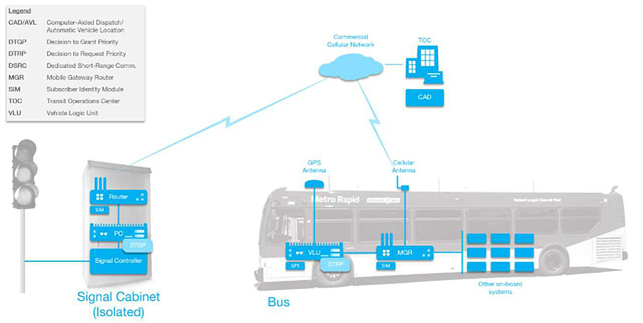
(Extended Text Description: Figure 2. V2I Cellular to Isolated Signal has a graphic showing an LA Metro Rapid bus in the lower right-hand side of the figure, a Signal Cabinet (Isolated) in the lower left-hand side of the slide, TOC graphic above the bus to the right, a cloud to the left of the TOC graphic, and legend in the upper left-hand corner of the figure. The front of the bus is pointed toward the left-hand side of the slide.
Inside the front of the bus is a graphic labeled "VLU." It is connected using a blue line to a graphic for a GPS antenna, which is sitting on top of the bus right above the VLU. There is a light blue box located in the lower right-hand part of the VLU labeled "DTRP" and a blue box under the VLU labeled "GPS."
Connected to the right of the VLU via a blue line is a graphic labeled "MGR." There is one small blue box right below the MGR labeled "SIM." The MGR is connected via a blue line to a graphic for a Cellular Antenna, which is sitting on top of the bus above the MGR. The MGR is connected via a blue line to nine unlabeled boxes to the right of the MGR representing other on-board systems.
The Cellular Antenna is connected to a cloud labeled "Commercial Cellular Network" via a lightning bolt. This cloud is connected to a graphic to its right representing a TOC via a blue line. Below the TOC is a blue box labeled "CAD."
The Commercial Cellular Network cloud is connected via a lightning bolt to the top of the Signal Cabinet (Isolated) which is located to the left of the bus. Within the Signal Cabinet are three elements on top of each other. The blue box at the bottom of the Signal Cabinet is labeled "Signal Controller." The Signal Controller is connected to a graphic representing a PC above the Signal Controller via a blue line. In the lower right-hand corner of the PC is a light blue box labeled "DTGP." The PC is connected via a blue line to a graphic representing a Router, which is right above the PC. The Router has a small blue box below it labeled "SIM."
The Signal Controller is connected to a traffic signal located to the left of the Signal Cabinet (Isolated) via a blue line.
The legend to the abbreviations on the slide is located in the upper left-hand corner of the figure as follows:
- CAD/AVL is Computer-Aided Dispatch/Automatic Vehicle Location
- DTGP is Decision to Grant Priority
- DTRP is Decision to Request Priority
- DSRC is Dedicated Short-Range Communication
- MGR is Mobile Gateway Router
- SIM is Subscriber Identity Module
- TOC is Transit Operations Center
- VLU is Vehicle Logic Unit
Figure 2. V2I Cellular to Isolated Signal (courtesy of Ed Alegre, LA Metro)
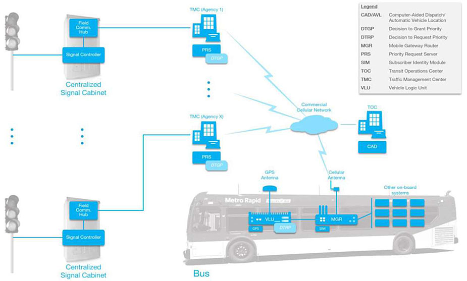
(Extended Text Description: Figure 3. V2C Cellular to Centralized TMC has a graphic showing an LA Metro, Metro Rapid bus in the lower right-hand side of the slide, a Signal Cabinet in the lower left-hand side of the slide, a Signal Cabinet in the upper left-hand side of the slide, a TMC graphic to the right of the Signal Cabinet in upper left-hand side of the slide, another TMC graphic just above the bus and to the right of the Signal Cabinet in the lower left-hand side of the figure, TOC graphic above the bus to the right, and a Commercial Cellular Network cloud to the left of the TOC. The front of the bus is pointed toward the left-hand side of the slide.
Inside the front of the bus is a graphic labeled "VLU." It is connected using a blue line to a graphic for a GPS antenna, which is sitting on top of the bus right above the VLU. There is a light blue box in the lower right-hand corner of the VLU labeled "DTRP." There is a blue box below the VLU to the left labeled "GPS."
Connected to the right of the VLU via a blue line is a graphic labeled "MGR." There is one small blue box right below the MGR labeled "SIM." The MGR is connected using a blue line to a graphic for a Cellular Antenna, which is sitting on top of the bus right above the MGR. The MGR is connected via a blue line to nine unlabeled boxes representing other on-board systems.
The Cellular Antenna is connected to a cloud labeled "Commercial Cellular Network" via a lightning bolt. This cloud is connected to a graphic to its right representing a TOC via a blue line. Below the TOC is a blue box labeled "CAD."
The Commercial Cellular Network cloud is connected via a lightning bolt to a graphic labeled "TMC (Agency X)." Below TMC (Agency X) is a blue box labeled "PRS." The PRS box contains a small light blue box labeled "DTGP." The TMC (Agency X) is connected via a blue line to a blue box inside of the Centralized Signal Cabinet (located in the lower left-hand side of the figure) labeled "Field Communication Hub." The Field Communication Hub is connected via a blue line to a blue box labeled "Signal Controller" located just below the Field Communication Hub inside the bottom of the Centralized Signal Cabinet. The Signal Controller is connected via a blue line to a traffic signal located to the left of the Centralized Signal Cabinet.
The "Commercial Cellular Network" cloud is also connected via a lightning bolt to a graphic labeled "TMC (Agency 1)." Below TMC (Agency 1) is a blue box labeled "PRS." The PRS box contains a small light blue box labeled "DTGP." The TMC (Agency 1) is connected via a blue line to a blue box inside of the Centralized Signal Cabinet (located in the upper left-hand side of the figure) labeled "Field Communication Hub." The Field Communication Hub is connected via a blue line to a blue box labeled "Signal Controller" located just below the Field Communication Hub inside the bottom of the Centralized Signal Cabinet. The Signal Controller is connected via a blue line to a traffic signal located to the left of this Centralized Signal Cabinet.
There are three blue dots between the traffic light in the upper left-hand side of the figure and the traffic light in the lower left-hand side of the figure.
There are three blue dots between the two Centralized Signal Cabinets.
There are three blue dots between the TMC (Agency 1) and TMC (Agency X).
The legend to the abbreviations located in the upper right-hand corner of the figure is as follows:
- CAD/AVL is Computer-Aided Dispatch/Automatic Vehicle Location
- DTGP is Decision to Grant Priority
- DTRP is Decision to Request Priority
- MGR is Mobile Gateway Router
- PRS is Priority Request Server
- SIM is Subscriber Identity Module
- TOC is Transit Operations Center
- TMC is Traffic Management Center
- VLU is Vehicle Logic Unit
Figure 3. V2C Cellular to Centralized TMC (courtesy of Ed Alegre, LA Metro)
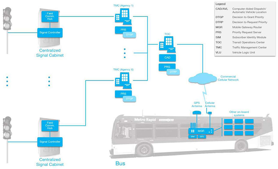
(Extended Text Description: Figure 4. C2C Fully Centralized TOC and TMC has a graphic showing an LA Metro, Metro Rapid bus in the lower right-hand side of the slide, a Signal Cabinet in the lower left-hand side of the slide, a Signal Cabinet in the upper left-hand side of the slide, a TMC graphic to the right of the Signal Cabinet in upper left-hand side of the slide, another TMC graphic just above the bus and to the right of the Signal Cabinet in the lower left-hand side of the figure, TOC graphic above the bus, and a Commercial Cellular Network cloud to the right of the TOC. The front of the bus is pointed toward the left-hand side of the slide.
Inside the middle of the bus is a graphic labeled "MGR." There are two small blue boxes right below the MGR labeled "SIM" and "GPS." The MGR is connected using a blue line to a graphic for a GPS Antenna, which is sitting on top of the bus right above the MGR. The MGR is also connected via a blue line to the graphic for a Cellular Antenna, which is sitting on top of the bus to the right of the GPS Antenna. The MGR is connected via a blue line to nine unlabeled boxes (located to the right of the MGR) representing other on-board systems.
The Cellular Antenna is connected to a cloud labeled "Commercial Cellular Network" via a lightning bolt. This cloud is connected to a graphic above it representing a TOC via a blue line. Below the TOC is a blue box labeled "CAD" and a blue box under the CAD box labeled "PRG." There is a light blue box in the lower right-hand part of the PRG labeled "DTRP."
The TOC is connected via a blue line to another blue line that connects two graphics representing two TMCs – one labeled "TMC (Agency 1)" located above the second labeled "TMC (Agency X)."
Below TMC (Agency 1) is a blue box labeled "PRS." The PRS box contains a small light blue box labeled "DTGP." The TMC (Agency 1) is connected via a blue line to a blue box inside of the Centralized Signal Cabinet (located in the upper left-hand side of the figure) labeled "Field Communication Hub." The Field Communication Hub is connected via a blue line to a blue box labeled "Signal Controller" located just below the Field Communication Hub inside the bottom of the Centralized Signal Cabinet. The Signal Controller is connected via a blue line to a traffic signal located to the left of this Centralized Signal Cabinet.
Below TMC (Agency X) is a blue box labeled "PRS." The PRS box contains a small light blue box labeled "DTGP." The TMC (Agency X) is connected via a blue line to a blue box inside of the Centralized Signal Cabinet (located in the lower left-hand side of the figure) labeled "Field Communication Hub." The Field Communication Hub is connected via a blue line to a blue box labeled "Signal Controller" located just below the Field Communication Hub inside the bottom of the Centralized Signal Cabinet. The Signal Controller is connected via a blue line to a traffic signal located to the left of the Centralized Signal Cabinet.
There are three blue dots between the traffic light in the upper left-hand side of the figure and the traffic light in the lower left-hand side of the figure.
There are three blue dots between the two Centralized Signal Cabinets.
There are three blue dots between the TMC (Agency 1) and TMC (Agency X).
The legend to the abbreviations located in the upper right-hand corner of the figure is as follows:
- CAD/AVL is Computer-Aided Dispatch/Automatic Vehicle Location
- DTGP is Decision to Grant Priority
- DTRP is Decision to Request Priority
- MGR is Mobile Gateway Router
- PRS is Priority Request Server
- SIM is Subscriber Identity Module
- TOC is Transit Operations Center
- TMC is Traffic Management Center
Figure 4. C2C Fully Centralized TOC and TMC (courtesy of Ed Alegre, LA Metro)
In addition to these four concepts, LA Metro developed a next generation TSP concept that has the "cloud" as the key component as shown in Figures 5, 6, and 7. For this LA Metro next-gen concept, the cloud performs four main functions:
- "Communicate with all TSP clients, including individual buses, transit management system, individual signals, and the traffic agency ATMS. Correlating bus route and schedule info with signal system info and signal locations, the cloud determines the correct signals to pass priority request messages to."
- "Using this correlated information, it converts request messages to the signal controller messaging standard as appropriate (NTCIP 1211 is the usual standard)."
- "Communicates the tailored priority request to the client applications at the ATMS or individual controllers."
- "Records and aggregates all actions taken on both the transit and signal side and performs analytics on the data to support performance monitoring and planning purposes."1
(Extended Text Description: Figure 5. TSP as a Service (TSPaaS) has a graphic showing an LA Metro, Metro Rapid bus in the lower right-hand side of the slide, a Signal Cabinet in the lower left-hand side of the slide, a Signal Cabinet in the upper left-hand side of the slide, TMC graphic to the right of the Signal Cabinet in upper left-hand side of the slide, TOC graphic above the bus to the right, and several clouds and a circle representing the Internet. The front of the bus is pointed toward the left-hand side of the slide.
Inside the front of the bus is a graphic labeled "VLU." It is connected using a blue line to a graphic for a GPS antenna, which is sitting on top of the bus right above the VLU. Connected to the right of the VLU via a blue line is a graphic labeled "MGR." There are two small blue boxes right below the MGR labeled "SIM" and "GPS.". The MGR is connected using a blue line to a graphic for a Cellular Antenna, which is sitting on top of the bus right above the MGR. The MGR is connected via a blue line to nine unlabeled boxes to the right of the MGR representing other on-board systems.
The Cellular Antenna is connected via a lightning bolt to a blue box labeled "CAD" which is located right below a TOC graphic. The Cellular Antenna is also connected to a cloud labeled "Commercial Cellular Network" via a lightning bolt. This cloud is connected to a graphic representing a Router inside of the Signal Cabinet that is located in the lower left-hand side of the slide. Right below this Router is a small blue box labeled "SIM." Connected to the Router via a blue line is a blue box right under the Router labeled "Signal Controller." This Signal Controller is connected to a traffic signal (located to the left of the Signal Controller) via a blue line.
The TOC is connected via a lightning bolt to a cloud labeled "Transit Operations Platform." In the lower right-hand corner of this cloud is a light blue box labeled "DTRP." This cloud is connected via a blue line labeled "API Access" to a gray circle labeled "Internet." The cloud labeled "Commercial Cellular Network" is connected to the same gray circle labeled "Internet" via a blue line.
The Signal Cabinet located in the upper left-hand side of the slide contains two blue boxes. The box in the top of the Signal Cabinet is labeled "Field Communication Hub." The Field Communication Hub is connected via a blue line to the blue box labeled "Signal Controller" which is located directly below the Field Communication Hub. The Signal Controller is connected to a traffic signal located to the left of the Signal Cabinet via a blue line.
The Signal Cabinet in the upper left-hand side of the slide is connected to a graphic representing a TMC via a blue line. The TMC is located to the right of this Signal Cabinet. The TMC is connected via a lightning bolt to a cloud labeled "Signal System Platform." There is a blue box labeled "DTGP" located in the lower right-hand portion of this cloud. This Signal System Platform cloud is connected via a blue line labeled "API Access" to the circle labeled "Internet."
Right above the TOC graphic is a legend to the abbreviations on the slide as follows:
- API is Application Programming Interface
- CAD/AVL is Computer-Aided Dispatch/Automatic Vehicle Location
- DTGP is Decision to Grant Priority
- DTRP is Decision to Request Priority
- MGR is Mobile Gateway Router
- PRS is Priority Request Server
- SIM is Subscriber Identity Module
- TOC is Transit Operations Center
- TMC is Traffic Management Center
- VLU is Vehicle Logic Unit
Figure 5. TSP as a Service (TSPaaS) (courtesy of Ed Alegre, LA Metro)
1 DKS Associates, "The Next Generation of Transit Signal Priority: Cloud Computing and the TSP-as-a-Service Model," presentation at 2017 ITS California Annual Meeting, September 30, 2017. Used with permission of DKS.
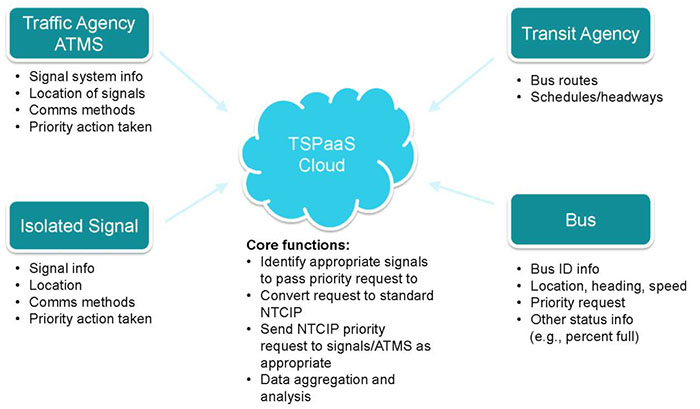
(Extended Text Description: Figure 6. TSP-as-a-Service Inputs has a cloud in the center of the figure labeled "TSPaaS Cloud." Under this cloud are the following words:
Core functions:
- Identify appropriate signals to pass priority request
- Convert request to standard NTCIP
- Send NTCIP priority request to signals/ATMS as appropriate
- Data aggregation and analysis
In the upper left-hand portion of the figure is a blue box labeled "Traffic Agency ATMS." A line with an arrow at the end connects this blue box to the TSPaaS Cloud. Under the Traffic Agency ATMS are the following:
- Signal system info
- Location of signals
- Comms methods
- Priority action taken
In the lower left-hand portion of the figure is a blue box labeled "Isolated Signal." A line with an arrow at the end connects this blue box to the TSPaaS Cloud. Under the Isolated Signal are the following:
- Signal info
- Location
- Comms methods
- Priority action taken
In the lower right-hand portion of the figure is a blue box labeled "Bus." A line with an arrow at the end connects this blue box to the TSPaaS Cloud. Under the Bus are the following:
- Bus ID info
- Location, heading, speed
- Priority request
- Other status info
- (e.g., percent full)
In the upper right-hand portion of the figure is a blue box labeled "Transit Agency." A line with an arrow at the end connects this blue box to the TSPaaS Cloud. Under the Transit Agency are the following:
- Bus routes
- Schedules/headways
Figure 6. TSP-as-a-Service Inputs (courtesy of Elliot Hubbard, DKS Associates)
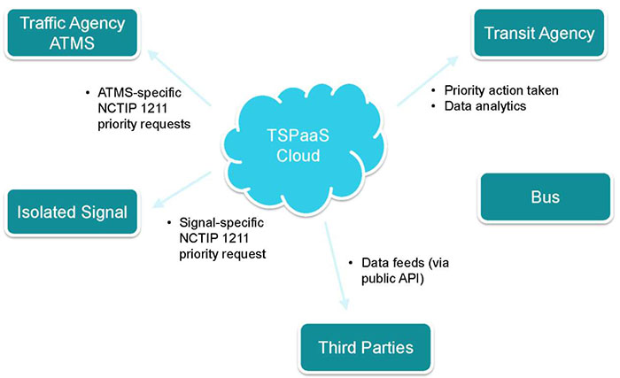
(Extended Text Description: Figure 7. TSP-as-a-Service Outputs has a cloud in the center of the figure labeled "TSPaaS Cloud."
In the upper left-hand portion of the figure is a blue box labeled "Traffic Agency ATMS." A line with an arrow at the end connects the TSPaaS Cloud to this box. Under the Traffic Agency ATMS is the following:
- ATMS-specific NCTIP 1211 priority requests
Below the Traffic Agency ATMS box is a blue box labeled "Isolated Signal." A line with an arrow at the end connects the TSPaaS Cloud to this box. Under the Isolated Signal is the following:
- Signal-specific NCTIP 1211 priority request
At the bottom of the figure is a blue box labeled "Third Parties." A line with an arrow at the end connects the TSPaaS Cloud to this box. Next to this box is the following:
- Data feeds (via public API)
In the middle right-hand portion of the figure is a blue box labeled "Bus." A line with an arrow at the end connects the TSPaaS Cloud to this box.
In the upper right-hand portion of the figure is a blue box labeled "Transit Agency." A line with an arrow at the end connects the TSPaaS Cloud to this box. Under the Transit Agency are the following:
- Priority action taken
- Data analytics
Figure 7. TSP-as-a-Service Outputs (courtesy of Elliot Hubbard, DKS Associates)
2.2. Capital District Transportation Authority (CDTA) Intelligent Transportation Management System (ITMS) - Albany, NY
The Capital District Transportation Authority (CDTA) in Albany, NY conducted a major procurement to replace their aging CAD/AVL system. Within this procurement, there was a requirement for OnBoard Mobile Routers/ Wireless Gateways. The requirement for On-board Mobile Gateway Routers (OMGRs) was included in the specifications in Section 5.2.3. This section of the specifications is contained on the next five pages.
Other portions of Request for Proposal referring to the OMGRs are as follows:
- Open Payment System Infrastructure - The Contractor shall partner with SPXGenfare to integrate open payments through CDTA’s new FastFare® electronic fareboxes via the Contractor’s ITMS on-board mobile gateway router. The purpose of this interface is to provide customers with on-board payment card transactions in real time.
- On BusPlus vehicles, Clever Devices IVN and mobile routers transmit vehicle location data to CD’s central prediction system (BusTime server).
- As described in section 5 "Wireless Data Communication Requirements," CDS wireless communications with ITMS on-board ITMS equipment, components, and devices shall be via the wireless mobile routers on-board vehicles and wireless access points at each operating division and select transit stations within the CDTA service area where CDTA has wide-area networking infrastructure.
- 4.7.3 On-Board Customer Wi-Fi. The Contractor shall provide on-board Wi-Fi enabled Internet access to customers as part of the ITMS On-board Mobile Gateway/Router (OMGR) on all CDTA vehicles.
Capital District Transportation Authority Intelligent Transportation Management System - Excerpts below:
Capital District Transportation Authority Intelligent Transportation Management System
5 Wireless Data Communication Requirements
5.1 General
The Contractor shall describe the data communication infrastructure required to satisfy the following communication needs for this project:
- Wireless data communication between vehicles located at the garages and the central system;
- Wireless data communication between the central system and fixed-route revenue vehicles;
- Wireless data communication between the central system and supervisor/support vehicles; and
- Wireless data communication between wayside Dynamic Message Signs (DMS) and the central system.
- Other Wireless data communication needs not otherwise explicitly identified but necessary to meet the functional specifications defined herein
The Contractor shall identify the specific on-board and central hardware and software that will be required to establish wireless communication infrastructure.
The Contractor shall identify the necessary cellular data requirements for their proposed solution and include pricing in the cost proposal.
The Contractor is encouraged to utilize the P25 Radio Communications System Enhanced Data feature to satisfy the wireless data communication functional specifications defined herein. Alternative wireless data communications solutions will be subject to CDTA approval prior to Contract Award.
The Contractor shall provide design documentation and demonstrations for the integration of the new P25 radio communications system for data radio and other wireless data communications requirements for CDTA review at the Preliminary Design Review and for approval at the Final Design Review. PDR FDR 5.1
5.2 Wireless Data Communications
5.2.1 Data Transfer
The Contractor shall describe the ITMS data communications between the CDS and all other ITMS systems, equipment, components, and devices (e.g. the mobile systems on vehicles). Data communications at stations/stops, and/or Kiosks shall be provided through an established commercial cellular service provider. The types of data to be communicated shall include, at minimum:
- AVL/VLU real-time location data (utilizing appropriate polling rates to satisfy the functional requirements defined herein)
- Real-time passenger information - predicted arrival times
- Text/Canned messages
- Covert Alarms
- Vehicle diagnostics
- Passenger Counts/Loads
- Schedule/Route/Run information
- TSP information
- Video Surveillance data
- Other ITMS parameters
The complete list of data transfer information requirements and design shall be provided to CDTA for review at the Preliminary Design Review and approval at the Final Design Review. PDR FDR 5.2.1
5.2.2 On-Board Hardware
5.2.2.1 Data Communication Hardware
The Contractor shall use the P25 Radio Communications System Enhanced Data features and the associated hardware for meeting the ITMS data communication needs on vehicles. In the event existing data radio hardware is insufficient in meeting the ITMS requirements, the Contractor shall present an alternate data radio solution for CDTAs approval prior to Contract Award.
5.2.2.2 Antenna Hardware
If applicable, proposed antenna hardware shall help limit the number of antenna hardware to be installed on each vehicle. An antenna which can support a combination of global positioning system (GPS) connections, cellular network connection and wireless fidelity (Wi-Fi) connection using a single unit (e.g., dual-mode antenna, tri-band antenna) may be used for the proposed solution. The Contractor must use low-profile antenna hardware.
5.2.2.3 Driver Handset and Speaker
The CAD/AVL vendor must integrate with the P25 Radio Communications System’s telephone handset with PTT button and a hang-up cup (e.g. Audio Sears or similar).
Vehicle operators shall be able to adjust the volume of the speaker at any time during the voice communication.
5.2.3 On-Board Mobile Router/Wireless Gateway 5.2.3.1 Hardware and Connectivity
The Contractor shall provide an On-board Mobile Gateway/Router (OMGR) for CDTA vehicles to accomplish wired and wireless connectivity.
The OMGR shall comply with on-board hardware requirements described herein. The OMGR shall provide the following connectivity capabilities:
- Cellular Modem: the OMGR shall be equipped with built-in modem card slots for cellular data connectivity, compliant with each major cellular carrier network available in the CDTA service area. The OMGR shall have at least three (3) built-in card slots. The OMGR shall accept cards compliant with Peripheral Component Interconnect (PCI) and Universal Serial Bus (USB) standards.
- Wi-Fi: The OMGR shall be equipped with built-in Institute of Electrical and Electronics Engineers (IEEE) 802.11x card for Wi-Fi Connectivity to an external access point.
- Ethernet: The OMGR shall be equipped with a built-in Ethernet adaptor for local area network (LAN) connectivity in-vehicle: The OMGR shall consist of at least four (4) built-in Ethernet ports and shall have the ability to extend to eight (8) Ethernet ports by utilizing an external network switch.
- Data Radio Connectivity: The OMGR shall have the ability to utilize the data connectivity link available from on-board Motorola APX IV&D Subscriber.
-
Additional Capabilities: The OMGR shall have the following additional capabilities.
- The OMGR shall have the ability to perform as a mobile hotspot
- The OMGR shall be equipped with at least two USB 2.0 connection ports
- The OMGR shall be equipped with at least one RS-232 connectivity port
- The OMGR shall have built-in information security capabilities (e.g., encryption) to protect the data routed over wired or wireless networks. At least, 128 bit W-Fi Protected Access (WPA or WPA2) encryption to avoid unauthorized access. Also, a built in firewall shall be included to deny malicious content but shall not block virtual private network access. The Contractor shall describe all built-in security capabilities as part of the PDR and FDR.
- The OMGR shall be capable of being managed and configured locally (via Ethernet) or remotely (via wireless network) and built in diagnostic capability and reporting on its status through a central management software program
- The OMGR shall support port filtering/blocking and port forwarding capabilities,
- The OMGR shall be designed for harsh transit vehicle environments and be shock resistant
- The OMGR shall be integrated into one unit to minimize the installation form factor on the vehicle
- The OMGR shall be connected to a low profile antenna designed for harsh transit vehicle environments
The Contractor shall provide the required OMGR ITMS data communications design to CDTA for review and demonstration at the Preliminary Design Review and approval at the Final Design Review. PDR FDR 5.2.3.1
5.2.3.2 OMGR Data Communications Requirements
The OMGR shall support quality of service (QoS) to ensure protected bandwidth for multiple sub-channels when multiple sub-channels are enabled for connectivity of individual on-board systems (e.g., CAD/AVL and video surveillance system).
The OMGR shall be configurable to control which on-board system can perform outbound communication based on the speed of data connection available at a given time (e.g., video transmission shall be allowed only when 4G cellular connectivity is available).
The OMGR shall have the ability to configure the data rate limits for inbound and outbound data communications.
The OMGR shall be able to automatically switch to an available network based on the agency configuration. The configuration parameters shall include but shall not be limited to available network(s) and their priorities, time of day, current geographic location and CDTA division. The OMGR shall automatically fallback to cellular communication in the event no data radio coverage is available.
The OMGR shall have the capability use port filtering/blocking to ensure only appropriate data traffic is routes on an available wireless network.
The port forwarding feature shall allow a host application at the central system (e.g., video Playback Software) to connect to a desired on-board system (e.g., DVR).
The OMGR shall support Dynamic Host Control Protocol (DHCP) for connected devices and provide the capability to turn on and off the DHCP server as needed.
The OMGR shall have at least ten (10) GB of built-in storage.
5.2.3.3 System Administration and Real-Time Management of OMGR
The Contractor shall provide OMGR central management software to enable authorized CDTA users the capability to manage and administer the following minimum features and functions of the OMGR.
- To block access to a website or group of websites
- To filter websites in real-time without rebooting the OMGR
- To provide real-time reporting on the Internet customer usage per vehicle and OMGR including URL, content type (e.g. file download, audio or video streaming) date, time, MAC address and total bandwidth used
- To configure and modify configuration parameters of the modem and router to improve performance
- To continuously receive communication updates on the status of the OMGR and modems
- To send and receive alerts on malfunctions and other administrative alerts
- To diagnose, reconfigure, reboot, and reset a malfunctioning router or modem remotely when the vehicle is not in revenue service
- To update the modem and/or router firmware or other software with patches, fixes or upgrades
5.2.3.4 OMGR MDT Connectivity
At minimum, the MDT shall be connected with the OMGR via Ethernet port for the following data exchange activities:
- Sending and receiving of CAD/AVL, APC, VCM data via available wireless networks
- Upload and download of data via WLAN at CDTA garages.
5.2.4 Central Wireless Communication Gateway Software 5.2.4.1 General
A wireless data communications gateway shall be established to carry data using CDTAs private radio data network. However, the system must have the ability to switch to an available cellular network using the OMGR, if configured by CDTA. In the event of cellular communication failure, the vendor shall establish a private secure tunnel configuration in coordination with the cellular carrier and CDTA.
The gateway shall have the ability to support multiple wireless networks, including private radio, cellular and Wi-Fi, simultaneously, if necessary.
The gateway shall be setup in a highly redundant configuration. The Contractor shall describe the redundancy functionality of the gateway.
The gateway shall provide the ability to monitor the communication traffic. Also, the gateway shall provide the ability to temporarily suspend the one-way or two-way wireless data communication path.
5.2.4.2 Data Message Processing
The system shall process data messages received from the vehicles and wayside digital message displays, and pass these messages to the central software.
The system shall process data messages received from the central software and pass these to an individual vehicle or a group of vehicles, or DMS, as applicable.
The system shall log and allow report generation on relevant details about each data message including but not limited to the following:
- Sender and receiver of a message;
- Type of the message; and
- Follow-up action to a message, if applicable (e.g., acknowledgement, voice call from dispatcher).
5.3 Garage Wireless Local Area Network (WLAN) Data Exchange
5.3.1 General
The Contractor shall supply, install, and configure a Garage Data Systems (GDS) and wireless data networks at each of the CDTA garage facilities where CDTA vehicles are parked and serviced. Via Wi-Fi communications, the GDS shall manage the secure and expedient transfer of all data transfers between the Central Data System and the ITMS equipment, components, and devices.
The system shall allow all ITMS static files including but not limited to schedules, announcements, service changes, firmware, parameters, configuration settings and other software to be set up so they will be automatically downloaded to vehicles when they connect with the WLAN, including a mechanism to avoid repeating a download to a vehicle that has already previously received it as well as to determine once all vehicles have received the download. The system shall automatically receive from vehicles once they connect to the WLAN any files they have ready for upload, including a mechanism to avoid repeating an upload from a vehicle that has already previously provided it.
The Contractor shall describe the bidirectional wireless data exchange design including all data transfers to and from the vehicle, vehicle coverage, location, and power requirements, and OMGR real-time data transfers and limitations, if applicable, with their proposal response.
2.3. Tri-County Metropolitan Transportation District of Oregon (TriMet) Hop Fastpass - Portland, OR
"The Tri-County Metropolitan Transportation District of Oregon (TriMet), the primary public transportation provider in Portland, [Oregon] utilized a novel approach to build the Hop Fastpass, its public transit payment system that first launched in 2017 and has steadily added new features."2
The next four pages show relevant portions of the specifications. The conceptual system diagram is shown on the page following the relevant portion of the specifications.
Another key requirement in the specifications is as follows: "The eFare system will be built using an account-based, open payment architecture with key system interfaces based on Application Programming Interfaces (APIs) that are published by the Contractor and fully owned or licensed by TriMet."
2 APTA MOBILITY INNOVATION PILOT OF THE MONTH: TriMet’s Hop Fastpass Open Architecture in Fare Payment, webinar conducted on June 27, 2019
Appendix A/eFare Sys IntTech Specs - 84 Oct. 3, 2013 - Excerpts below:
| 6.2.1-8 | Validators will be remotely configurable and managed through the system monitoring and management application (see Section 6.1.3). Validator software and configuration, including all white lists and hotlists will be managed through this system. | CDRL6-12 |
6.2.2 Communications
| Req# | Requirement | Assigned CDRL(s) |
|---|---|---|
| 6.2.2-1 | Onboard validators will be designed with an Ethernet port that enables connection to existing mobile data routers installed on TriMet and C-TRAN buses. Where available, the mobile data routers will serve as primary means of off-board communication with the eFare back office. | CDRL6-12 CDRL6-13 |
| 6.2.2-2 | Platform validators will be designed with an Ethernet port that enables direct connection to the eFare back office. | CDRL6-12 CDRL6-13 |
| 6.2.2-3 | All validators will include an embedded cellular communications interface that supports third generation (3G GSM/CDMA) and fourth generation (4G) Long-Term Evolution (LTE) data networks on all major U.S. carriers. The embedded cellular communications will be used in instances where a mobile data router or Ethernet connection is not available. | CDRL6-12 CDRL6-13 |
| 6.2.2-4 | All validators will include Wi-Fi (802.11a/b/g/n/ac) communications to enable integration with other systems, exchange of non-critical data at designated locations, and sharing of data connections on vehicles and at rail platforms. | CDRL6-12 CDRL6-13 |
| 6.2.2-5 | Validators will be designed with a spare USB port to support the future connection of an ancillary device, such as a barcode reader. | CDRL6-12 |
6.2.3 CAD/AVL Integration
| Req# | Requirement | Assigned CDRL(s) |
|---|---|---|
| 6.2.3-1 | Contractor shall be responsible for integration of the onboard payment validator with the INIT CAD/AVL system installed on TriMet and C-TRAN vehicles. The integration will use the Contractor-supplied CAD/AVL Integration API (see Section 2.2.3.8) and the embedded communication interfaces. | CDRL6-12 CDRL6-13 |
| 6.2.3-2 | Integration with the CAD/AVL systems will support single sign-on, the capture of geo-location data, and provide an auxiliary display and input device for the eFare system through the CAD/AVL operator control unit. | CDRL6-13 |
| 6.2.3-3 | Single sign-on will enable the CAD/AVL login and routing data, including operator ID, pattern, block, route, and direction, to be captured by the eFare validator. The login and routing data will be appended to every fare transaction generated by the eFare validator. | CDRL6-13 |
| 6.2.3-4 | The eFare validator will capture geo-location data generated by the CAD/AVL system, including Bus Stop ID and GPS coordinates. The geo-location data will be appended to every fare transaction generated by the eFare validator. Validators will also include an embedded global positioning system (GPS) receiver, and append local GPS coordinate information to each eFare transaction, in addition to and geo-location data provided by the CAD/AVL system. | CDRL6-13 |
| 6.2.3-5 | The CAD/AVL operator control unit will display fare payment results transmitted from the eFare validator, including fare payment approval or denial, and the case of approval, fare product and fare category associated with the transit account (e.g., adult, youth, or honored citizen) used for payment. | CDRL6-13 |
| 6.2.3-6 | The CAD/AVL operator control unit will be able to initiate a fare override function that will cause eFare validator to flag a fare transaction so that it is priced at a reduced fare, even if a full fare account is being used for payment. The fare override function will be configurable to support both open and closed-loop payments. | CDRL6-13 |
6.2.4 Transaction Processing
| Req# | Requirement | Assigned CDRL(s) |
|---|---|---|
| 6.2.4-1 | The eFare validators will automatically and continuously poll for all supported media formats. | CDRL6-13 |
| 6.2.4-2 | The eFare validators will be equipped with real-time communication to AMPS for the processing of fare payments using the Contractor-supplied fare payment API (see Section 2.2.3.3). | CDRL6-12 CDRL6-13 |
| 6.2.4-3 | Prior to transmitting a fare payment transaction to AMPS, the validators will perform local fare media validity checks, including checks against any locally maintained white lists and hotlists, as deemed necessary for security and the efficient processing of transactions. | CDRL6-13 |
| 6.2.4-4 | Validators will provide a payment result within 500 milliseconds of valid fare media being presented for all fare payment types. | CDRL6-12 CDRL6-13 |
| 6.2.4-5 | Validators will display fare payment results, including approval or denial, fare paid, fare product used for payment, remaining account balance, time remaining on transfers, and fare capping status, for all fare payments. | CDRL6-13 |
| 6.2.4-6 | Validators will be able to accept fare payments in an offline mode, and accommodate scenarios where a full authorization cannot be received within the required timeframe. In these scenarios, risk mitigation strategies will be employed to limit exposure for declined payments. | CDRL6-12 CDRL6-13 |
| 6.2.4-7 | Validators will provide no indication to the customer or operator when they are operating in offline mode. | CDRL6-12 CDRL6-13 |
| 6.2.4-8 | Validators will maintain a whitelist of all media linked to reduced fare accounts to enable indication of a reduced fare payment via the CAD/AVL operator control unit, even when the validator is operating in offline mode. | CDRL6-12 CDRL6-13 |
| 6.2.4-9 | All transactions generated in an offline mode will be sent to AMPS immediately upon restoration of communications. | CDRL6-12 CDRL6-13 |
| 6.2.4-10 | Validators will support an anti-collision algorithm to ensure that payment is only accepted from a single piece of media when multiple valid pieces of media are presented. | CDRL6-13 |
| 6.2.4-11 | The transaction processing algorithm will be subject to agency review and approval during design review. | CDRL6-12 CDRL6-13 |
6.2.5 User Interface
| Req# | Requirement | Assigned CDRL(s) |
|---|---|---|
| 6.2.5-1 | Validators will include a full color displays that supports adjustable brightness and contrast, and can be easily read under any combination of ambient lighting, including direct sunlight and night-time operation. | CDRL6-11 |
| 6.2.5-2 | Validators will include at least three (3) multicolor LED indicator lights that can be configured to provide feedback on payment and device status. | CDRL6-11 |
| 6.2.5-3 | Validators will include an audio interface and speakers for customizable audio feedback, including varying tones and full speech. | CDRL6-11 |
| 6.2.5-4 | Platform validators will include a 3.5mm headphone jack capable of providing customizable audio feedback. | CDRL6-11 |
| 6.2.5-5 | The visual and audio interfaces will provide visual and audible feedback on fare payment and device status that meets all ADA requirements. | CDRL6-11 CDRL6-12 |
| 6.2.5-6 |
Voice annunciation of the fare charged and remaining account balance will be separately configurable as follows:
|
CDRL6-11 CDRL6-12 |
| 6.2.5-7 | All validator visual and audio output will be fully configurable and subject to agency review and approval during design review | CDRL6-11 CDRL6-12 |
6.2.6 Electronic Storage
| Req# | Requirement | Assigned CDRL(s) |
|---|---|---|
| 6.2.6-1 | Validators will include sufficient embedded storage to hold thirty (30) days of fare payment transactions, and a hotlist or whitelist equivalent to 75% of total media issuance, at the anticipated maximum usage of the system. | CDRL6-11 CDRL6-12 |
| 6.2.6-2 | Validators will support expandable storage in a common, commercially available format (e.g., compact flash, secure digital, etc.) that can be easily swapped or expanded without modification to the rest of the device components. | CDRL6-11 CDRL6-12 |
| 6.2.6-3 | Validators will generate an alarm through the system monitoring and management application (see Section 6.1.3) and provide a visual indication if a failure of either the primary or backup data storage occurs. | CDRL6-12 |
| 6.2.6-4 | An alternate means of removing data from the validator device will provided for instances where the there is a failure of the wired or wireless communication or power supply. | CDRL6-11 CDRL6-12 |
| 6.2.6-5 | Where it is necessary to store sensitive data, including all transaction data, white lists and hotlists, validators will do so in a PCI-compliant manner. | CDRL6-11 CDRL6-12 |
6.2.7 Finish/Mounting
| Req# | Requirement | Assigned CDRL(s) |
|---|---|---|
| 6.2.7-1 | Validators will be rugged and function under environmental conditions including: direct sunlight, dust/grit/sand, humidity, electrical storms, exposure to urban environment, and the range of elevations and altitudes in the operation region (see Section 3.3). | CDRL6-11 |
| 6.2.7-2 | Validator housing will be resistant to corrosion, abrasion, scratching, impacts, and vandalism. | CDRL6-11 |
| 6.2.7-3 | Validator housing color and finish will be such that it minimizes reflection and is highly resistant to fading, cracking, and peeling. | CDRL6-11 |
| 6.2.7-4 | All validator corners will be rounded, and there will be no exposed bolt heads, nuts, sharp edges, or cracks on outside surfaces. | CDRL6-11 |
| 6.2.7-5 | Validator displays will be flush mounted in the housing. | CDRL6-11 |
| 6.2.7-6 | Covers on the validator housing for accessing modules and subassemblies will be secured with mechanical locks and keys that are not readily duplicated, nor readily available to the public, and uniquely serialized and stamped "Do Not Duplicate." | CDRL6-11 |
Appendix A/eFare Sys IntTech Specs
86 Oct. 3, 2013
Figure 2-1 Conceptual System Diagram
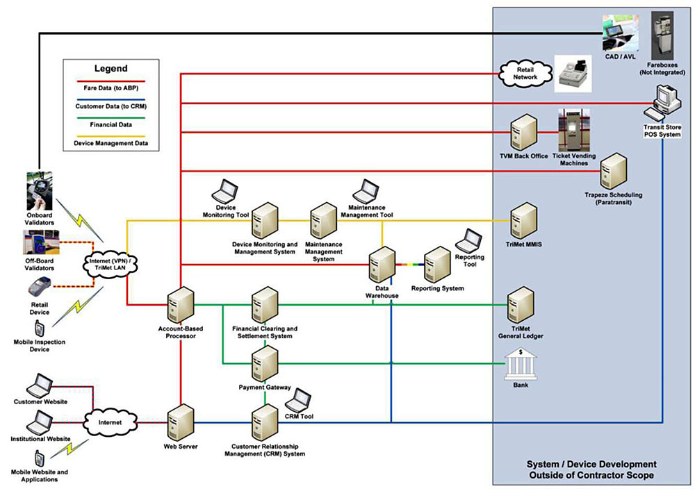
(Extended Text Description: The figure labeled Figure 2-1. Conceptual System Diagram has a flowchart describing TriMet’s fare system.
There is a legend in the upper right-hand corner of the slide showing the following:
- A red line is Fare Data (to ABP)
- A blue line is Customer Data (to CRM)
- A green line is Financial Data
- A yellow line is Device Management Data
On the far left of the flowchart excerpt are four boxes. From top to bottom, the boxes are labeled "On-board Validators," "Off-board Validators," "Retail Device" and "Mobile Inspection Device." The On-board Validators box is connected via a lightning bolt to a cloud graphic with the words "Internet (VPN)/TriMet LAN" inside of it. The Off-board Validators and Retail Devices boxes are connected to this cloud via red dashed lines. The Mobile Inspection Device is connected via a lightning bolt to this cloud.
The Internet (VPN)/TriMet LAN cloud is connected via a yellow line to a computer labeled "Device Monitoring and Management System" located to the right of this cloud. This computer is connected via a yellow line to a computer labeled "Maintenance Management System" which is located to the right of the Device Monitoring and Management System. The Maintenance Management System is connected via a yellow line to a computer labeled "TriMet MMIS" and via a yellow line to a computer labeled "Data Warehouse."
Above and to the left of the Device Monitoring and Management System is a laptop graphic labeled "Device Monitoring Tool." Above and to the right of the Maintenance Management System is a laptop graphic labeled "Maintenance Management Tool."
The Internet (VPN)/TriMet LAN cloud is connected via a red line to a computer labeled "Account-based Processor." The Account-based Processor is connected via a green line to a computer labeled "Financial Clearing and Settlement System." The Financial Clearing and Settlement System is connected via a green line to a computer labeled "Data Warehouse."
The Data Warehouse is connected via all four colors to a computer labeled "Reporting." Located above and to the right of Reporting is a laptop labeled Reporting Tool.
The Account-based Processor is connected via a red line to a computer labeled "Web Server," which is located directly below the Account-based Processor. The Web Server is connected via a red and blue line to a cloud located to the left of the Web Server labeled "Internet." This cloud is connected via red and blue lines to two laptops labeled "Customer Website" and "Institutional Website" located to the left of this cloud. This cloud is also connected via a lightning bolt to a graphic representing Mobile Website and Applications, which is located directly below the Institutional Website laptop.
The Web Server is connected via a blue line to a computer labeled "Customer Relationship Management (CRM) System," which is located to the right of the Web Server. The CRM System is connected via a green line to a computer labeled "Payment Gateway," which is located directly above the Web Server. Above and to the right of the CRM System is a laptop labeled "CRM Tool." The Payment Gateway is connected via a green line to the computer labeled "Financial Clearing and Settlement System," which is located directly above the Payment Gateway. The Payment Gateway is also connected to the Account-based Processor via a green line. The Payment Gateway is connected via a green line to a graphic representing a Bank.
The CRM System is connected via a blue line to the Data Warehouse. The CRM System is connected via a blue line to the computer labeled "Transit Store POS System," which is located under Fareboxes (Not Integrated). The Account-based Processor is connected via a red line to the Transit Store POS System as well.
The Financial Clearing and Settlement System is connected via a green line to a computer labeled "TriMet General Ledger," which is located to the right of the Financial Clearing and Settlement System, and directly under the TriMet MMIS.
The Account-based Processor is connected via a red line to a computer labeled "Trapeze Scheduling (Paratransit)," which is located directly under the Ticket Vending Machines.
The Account-based Processor is connected via a red line to a computer labeled "TVM Back Office." The TVM Back Office is connected via a red line to a box labeled "Ticket Vending Machine."
The Account based Processor is connected via a red line to a cloud labeled "Retail Network." To the right of this cloud is a cash register graphic.
On-board Validators are connected via a black line to a graphic labeled "CAD/AVL," which is located directly above the cash register graphic. To the right of the CAD/AVL is a graphic labeled "Fareboxes (Not Integrated)," which is located directly above the Transit Store POS System.
A light blue box labeled "System / Device Development Outside of Contractor Scope" is overlaid over several flowchart elements on the right-hand side of the figure. These elements from top of the overlay to the bottom are: CAD/AVL and Fareboxes (Not Integrated); Retail Network cloud and cash register graphic; Transit Store POS System; TVM Back Office and Ticket Vending Machines; Trapeze Scheduling (Paratransit); TriMet MMIS; TriMet General Ledger; and the Bank.)
Appendix A/eFare Sys IntTech Specs 20 Oct. 3,2013
3. Reference to Other Standards
3.1. IEEE 802.11
802.11 [and 802.11x] refers to a family of specifications developed by the IEEE for wireless [local area network] LAN (WLAN) technology. 802.11 specifies an over-the-air interface between a wireless client and a base station or between two wireless clients.
There are several specifications in the 802.11 family:
- 802.11 applies to wireless LANs and provides 1 or 2 [megabits per second] Mbps transmission in the 2.4 [gigahertz] GHz band using either frequency hopping spread spectrum (FHSS) or direct sequence spread spectrum (DSSS).
- 802.11a an extension to 802.11 that applies to wireless LANs and provides up to 54-Mbps in the 5GHz band. 802.11a uses an orthogonal frequency division multiplexing encoding scheme rather than FHSS or DSSS.
- 802.11b (also referred to as 802.11 High Rate or Wi-Fi) an extension to 802.11 that applies to wireless LANS and provides 11 Mbps transmission (with a fallback to 5.5, 2 and 1-Mbps) in the 2.4 GHz band. 802.11b uses only DSSS. 802.11b was a 1999 ratification to the original 802.11 standard, allowing wireless functionality comparable to Ethernet.
- 802.11e a wireless draft standard that defines the Quality of Service (QoS) support for LANs, and is an enhancement to the 802.11a and 802.11b wireless LAN (WLAN) specifications. 802.11e adds QoS features and multimedia support to the existing IEEE 802.11b and IEEE 802.11a wireless standards, while maintaining full backward compatibility with these standards.
- 802.11g applies to wireless LANs and is used for transmission over short distances at up to 54-Mbps in the 2.4 GHz bands.
- 802.11n 802.11n builds upon previous 802.11 standards by adding multiple-input multiple-output (MIMO). The additional transmitter and receiver antennas allow for increased data throughput through spatial multiplexing and increased range by exploiting the spatial diversity through coding schemes like Alamouti coding. The real speed would be 100 Mbit/s (even 250 Mbit/s in PHY level), and so up to 4-5 times faster than 802.11g.
- 802.11ac 802.11ac builds upon previous 802.11 standards, particularly the 802.11n standard, to deliver data rates of 433Mbps per spatial stream, or 1.3Gbps in a three-antenna (three stream) design. The 802.11ac specification operates only in the 5 GHz frequency range and features support for wider channels (80MHz and 160MHz) and beamforming capabilities by default to help achieve its higher wireless speeds. This standard is being used currently for new wireless access points (WAPs) in transit garages and facilities in order to upload or download data and software updates.
- 802.11ac Wave 2 802.11ac Wave 2 is an update for the original 802.11ac spec that uses [multiple user] MU-MIMO technology and other advancements to help increase theoretical maximum wireless speeds for the spec to 6.93 Gbps.
- 802.11ad 802.11ad is a wireless specification under development that will operate in the 60GHz frequency band and offer much higher transfer rates than previous 802.11 specs, with a theoretical maximum transfer rate of up to 7Gbps (Gigabits per second).
- 802.11ah Also known as Wi-Fi HaLow, 802.11ah is the first Wi-Fi specification to operate in frequency bands below one gigahertz (900 MHz), and it has a range of nearly twice that of other Wi-Fi technologies. It’s also able to penetrate walls and other barriers considerably better than previous Wi-Fi standards.
- 802.11r - 802.11r, also called Fast Basic Service Set (BSS) Transition, supports VoWi-Fi handoff between access points to enable VoIP roaming on a Wi-Fi network with 802.1X authentication.3
- 802.11p is one of the recent approved amendments to the IEEE 802.11 standard to add wireless access in vehicular environments (WAVE). It appended some enhancements to the latest version of 802.11 that required to support applications of Intelligent Transportation Systems (ITS). This includes data exchange between high-speed vehicles and between the vehicles and the roadside infrastructure in the licensed ITS band.4
3.2. Payment Card Industry Security Standards
Information regarding these standards are shown in the next two pages.
3 https://www.webopedia.com/TERM/8/802 11.html- content is no longer available.
4 http://www.iaeng.org/publication/WCECS2014/WCECS2014 pp691-698.pdf- content is no longer available.
Payment Card Industry Security Standards - Excerpts below:

Payment Card Industry Security Standards
PCI security standards are technical and operational requirements set by the Payment Card Industry Security Standards Council to protect cardholder data. The standards globally govern all merchants and organizations that store, process or transmit this data - with new requirements for software developers and manufacturers of applications and devices used in those transactions. Compliance with the PCI set of standards is mandatory for their respective stakeholders, and is enforced by the major payment card brands who established the Council: American Express, Discover Financial Services, JCB International, MasterCard Worldwide and Visa Inc.
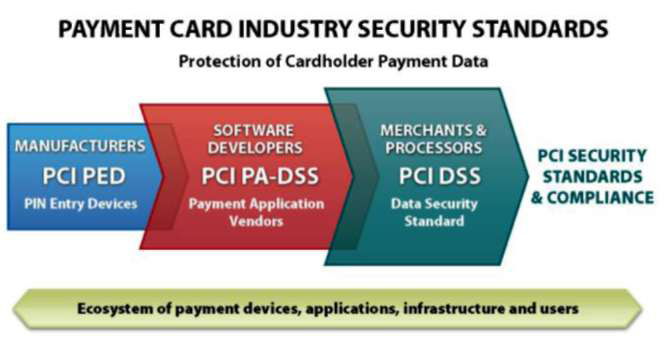
(Extended Text Description: There is a graphic at the top right of this page. At the top of the graphic are the words "Payment Card Industry Security Standards." Right below that are the words in smaller font "Protection of Cardholder Payment Data." Right below these words are three rectangles from left to right labeled as follows:
- Light blue rectangle labeled "Manufacturers." Under Manufacturers, it says "PCI Ped." Under PCI PED, it says "PIN Entry Devices."
- Red rectangle labeled "Software Developers." Under Software Developers, it says "PCI PA-DSS." Under PCI PA DSS, it says "Payment Application Vendors."
- Dark green rectangle labeled "Merchants and Processors." Under Merchants and Processors, it says "PCI DSS." Under PCI DSS, it says "Data Security Standard."
To the right of the last rectangle are the words "PCI Security Standards & Compliance. In a line under all three rectangles says "Ecosystem of payment devices, applications, infrastructure and users.")
PCI Standards Include:
PCI Data Security Standard: The PCI DSS applies to any entity that stores, processes, and/or transmits cardholder data. It covers technical and operational system components included in or connected to cardholder data. If your business accepts or processes payment cards, it must comply with the PCI DSS.
PIN Entry Device Security Requirements: PCI PED applies to manufacturers who specify and implement device characteristics and management for personal identification number (PIN) entry terminals used for payment card financial transactions.
Payment Application Data Security Standard: The PA-DSS is for software developers and integrators of applications that store, process or transmit cardholder data as part of authorization or settlement. It also governs these applications that are sold, distributed or licensed to third parties.

Participating Organizations
Merchants, banks, processors, developers and point of sale vendors
PCI Data Security Standard for Merchants & Processors
The PCI DSS is the global data security standard that any business of any size must adhere to in order to accept payment cards. It presents common sense steps that mirror best security practices.
| Goals | PCI DSS Requirements |
|---|---|
| Build and Maintain a Secure Network |
|
| Protect Cardholder Data |
|
| Maintain a Vulnerability Management Program |
|
| Implement Strong Access Control Measures |
|
| Regularly Monitor and Test Networks |
|
| Maintain an Information Security Policy |
|
COMPLIANCE PROGRAM
Assessing
Secure collection and tamper-proof storage of cardholder data; it must be available for analysis
Reporting
Prove compliance if assessed and present evidence that data protection controls are in place
Monitoring & Alerting
Have systems for auto-alerting to constantly monitor access and usage of data
Systems should extend to log data with proof of being collected and stored
PCI AT-A-GLANCE
(visit www.pcisecuritystandards.org/ for more information)
Overview
Getting Started with PCI DSS
10 Common Myths of PCI DSS
Data Security Do’s and Dont’s
Getting Started with PA-DSS
Getting Started with PCI PED
How to Comply with PCI DSS
The PCI Security Standards Council sets the standards for PCI security but each payment card brand has its own program for compliance. Specific questions about compliance should be directed to your acquiring financial institution. Links to payment card brand compliance program include:
- American Express: www.americanexpress.com/us/merchant/us-data-security.html
- Discover Financial Services: www.discoverglobalnetwork.com/en-us/
- JCB International: www.jcbusa.com/
- MasterCard Worldwide: www.mastercard.us/en-us/business/overview/safety-and-security/security-recommendations/site-data-protection-PCI.html
- Visa Inc: usa.visa.com/support/small-business/security-compliance.html?ep=v_sym_cisp (U.S.)
Qualified Assessors. The Council provides programs for two kinds of certifications: Qualified Security Assessor (QSA) and Approved Scanning Vendor (ASV). QSAs are companies that assist organizations in reviewing the security of its payments transaction systems and have trained personnel and processes to assess and validate compliance with PCI DSS and PA-DSS. ASVs provide commercial software tools to perform certified vulnerability scans for your systems. Additional details can be found on our Web site at: www.pcisecuritystandards.org/.
Self-Assessment Questionnaire. The "SAQ" is a validation tool for merchants and service providers who are not required to do on-site assessments for PCI DSS compliance. Different SAQs are specified for various business situations; more details can found on our Web site at: www.pcisecuritystandards.org or contact the acquiring financial institution to determine if you should complete an SAQ.
Payment Application Data Security Standard for Developers
The PA-DSS minimizes vulnerabilities in payment applications. The goal is to prevent the compromise of full magnetic stripe data located on the back of a payment card. PA-DSS covers commercial payment applications, integrators and service providers. Merchants and service providers should use certified payment applications and should check with their acquiring financial institution to understand requirements and associated timeframes for compliance.
| Payment Application DSS Requirements - Validated by PA-QSA Assessment |
|---|
| 1. Do not retain full magnetic stripe, card validation code or value (CAV2, CID, CIV2, CW2) or PIN block data |
| 2. Provide secure password features |
| 3. Protect stored cardholder data |
| 4. Log application activity |
| 5. Develop secure applications |
| 6. Protect wireless transmissions |
| 7. Test applications to address vulnerabilities |
| 8. Facilitate secure network implementation |
| 9. Do not store cardholder data on a server connected to the Internet |
| 10. Facilitate secure remote software updates |
| 11. Facilitate secure remote access to application |
| 12. Encrypt sensitive traffic over public networks |
| 13. Encrypt all non-console administrative access |
| 14. Maintain instructional documentation and training programs for customers, resellers and integrators |
PIN Entry Device (PED) Security Requirements for Manufacturers
This standard, referred to as PED, applies to companies which make devices that accept personal identification number (PIN) entry for all PIN-based transactions. Merchants and service providers should use certified PED devices and should check with their acquiring financial institution to understand requirements and associated timeframes for compliance.
| PIN Entry Device Security Requirements - Validated by PED Laboratory |
|---|
| Device Characteristics |
| Physical Security Characteristics (to prevent the device from being stolen from its location) |
| Logical Security Characteristics (to provide functional capabilities that ensure the device is working appropriately) |
| Device Management |
| Device Management during manufacturing |
| Device Management between manufacturer and initial cryptographic key loading |
| Considers how the PED is produced, controlled, transported, stored and used throughout its lifecycle (to prevent unauthorized modifications to its physical or logical security characteristics) |
© 2008 PCI Security Standards Council LLC. The intent of this document is to provide supplemental information, which does not replace or supersede PCI SSC Security Standards or their supporting documents.
4. Case Studies
There are no new case studies in this module in addition to the following three presented in the module:
- Case study of procuring and implementing CAD/AVL system using a mobile router/ wireless gateway as part of the Capital District Transportation Authority (CDTA) (Albany, NY) Intelligent Transportation Management System (ITMS)
- Case study of procuring system requiring on-board integration and transaction processing as part of the Tri-County Metropolitan Transportation District of Oregon (TriMet) (Portland, OR) Hop Fastpass
- Case study of migrating to using current communication technology at Alameda-Contra Costa Transit District (AC Transit) in Oakland, CA
5. Glossary
| Term | Definition |
|---|---|
| Automatic vehicle location (AVL) | The central software used by dispatchers for operations management that periodically receives real-time updates on fleet vehicle locations. In most modern AVL systems this involves an onboard computer with an integrated Global Positioning System receiver and mobile data communications capability. |
| Computer-aided Dispatch (CAD) | CAD software integrates transit operations by giving transit dispatchers and supervisors’ decision support tools to manage the operating environment. |
| Global System for Mobile communication (GSM) | GSM is a digital mobile network that is widely used by mobile phone users in Europe and other parts of the world. GSM digitizes and compresses data, then sends it down a channel with two other streams of user data, each in its own time slot. |
| Infrastructure as a Service (IaaS) | Cloud layer offering that enables a self-service model for managing virtualized data center infrastructure. Customers pay for on-demand access to pre-configured computing resources, such as network, storage, and operating systems. |
| Internet of Things (IoT) | The interconnection via the Internet of computing devices embedded in everyday objects, enabling them to send and receive data. |
| Internet Protocol (IP) | A set of rules governing the format of data sent over the Internet or other network. |
| Long Term Evolution (LTE) | LTE is a standard for 4G wireless broadband technology that offers increased network capacity and speed to mobile device users. It also provides reduced latency, scalable bandwidth capacity and backward-compatibility with existing GSM and UMTS technology. |
| Mobile Gateway Router (MGR) [also known as On-board MGR and mobile access router] | Wireless gateways work in the cellular radio space and add intelligence to the activity of connecting a device to the internet. They will translate a private local IP to a public network IP assigned by the cellular service carrier. The gateway connects a local private device or local private network to the carrier’s public network and the internet. Mobile gateway routers perform all the functions of a wireless gateway, and add sophisticated routing capabilities as well as multiple Ethernet and/or WLAN connections. These capabilities involve port forwarding or mapping and port routing. The single public IP assigned from the carrier may be mapped in the router so that one port of the single public IP is mapped to a camera, another to a sensor, and another to manage the router, and another to a locally connected network for web access. Often these two devices can be combined into one and referred to as an on-board mobile gateway router (OMGR). |
| Open Systems Interconnection (OSI) | The OSI model is a conceptual framework that describes the functions of a networking or telecommunication system. |
| Platform as a Service (PaaS) | Cloud layer offering that provides tools and other computing infrastructure, enabling organizations to focus on building and running web applications and services. PaaS environments primarily support developers, operations, and hybrid teams. |
| Quality of service (QoS) | QoS is a family of evolving Internet standards that provides ways to give preferential treatment to certain types of Internet Protocol (IP) traffic. |
| Software as a Service (SaaS) | Applications hosted by a third party and usually delivered as software services over a web browser that is accessed on the client’s side. |
| Transit signal priority (TSP) | TSP is a general term for a set of operational improvements that use technology to reduce dwell time at traffic signals for transit vehicles by holding green lights longer or shortening red lights. |
| Universal Mobile Telecommunications Service (UMTS) | UMTS is a third-generation (3G) broadband, packet-based transmission of text, digitized voice, video, and multimedia at data rates up to 2 megabits per second (Mbps). |
| Vehicle logic unit (VLU) | Typically, the VLU within the mobile data terminal (MDT) provides the processing power needed to support automation, single point log-on, and other onboard transit ITS applications. |
| Wide area network (WAN) | A computer network in which the computers connected may be far apart, generally having a radius of half a mile or more. |
6. References
-
Module 19 On-board Transit Management Systems for Buses. Module 19 can be found at
StandardsTraining/modtransit19/ppt/mt19ppt.pdf - Anthony Incorvati, Axis Communication, "Innovations in IP Video," presented at APTA BUS 2018, May 8, 2018.
- https://usatcorp.com/m2m-modem-gateway-and-router-differences/
- Don Murphy, IBI Group, "Emerging On-board Transit Architectures & Implications: An Exciting Opportunity," presentation at the 2018 ITS California Annual Meeting
- Metro Transit Agency Keeps GPS Connected for Accurate Real-Time Information," Cradlepoint Case Study, https://web-qa.cradlepoint.com/sites/default/files/valley-ride-cs-3.pdf
- Elliot Hubbard, DKS, "The Next Generation of Transit Signal Priority: Cloud Computing and the TSP-as-a-Service Model," presented at the 2017 ITS California Annual Meeting
- "Next Generation Bus Signal Priority," by Ed Alegre, Los Angeles County Metropolitan Transportation Authority (LA Metro) at an ITS California Meeting
- APTA MOBILITY INNOVATION PILOT OF THE MONTH: TriMet’s Hop Fastpass Open Architecture in Fare Payment, webinar conducted on June 27, 2019
- "Portland/Vancouver eFare System Integrator Technical Specifications," Oct. 3, 2013
- "The role of connectivity in overhauling bus operations and improving rider experience," Intelligent Transport, September 3, 2019 issue, pp. 48-50
- Ahsan Baig, Chief Information and Technology Officer, Alameda-Contra Costa Transit District "Connected Bus - Digital Journey For Analog Voice," presentation at 2019 ITS California Annual Meeting, September 9-11, 2019, Los Angeles, CA
- Portland Bureau of Transportation, Ubiquitous Mobility for Portland, Proposal for U.S. Department of Transportation Beyond Traffic: The Smart City Challenge, Volume 1: Technical Application, May 24, 2016
- Shaheen, Susan, PhD; Totte, Hannah and Stocker, Adam, "Future of Mobility White Paper," https://escholarship.org/uc/item/68g2h1qv, 2018, DOI: 10.7922/G2WH2N5D
- Virginia Tech Transportation Institute (VTTI), University of Virginia (UVA) Center for Transportation Studies and Morgan State University (MSU), "Applications of Connected Vehicle Infrastructure Technologies to Enhance Transit Service Efficiency and Safety," prepared for the
- Research and Innovative Technology Administration (RITA); U.S. Department of Transportation (US DOT), September 30, 2016
- Gabriel Lopez-Bernal, Carol Schweiger, Amy Jacobi and John L. Craig, Transit Traveler Information Infrastructure Mobility Application: Operational Concept, prepared for USDOT ITS-Joint Program Office, June 2015
- "’INFOtransit’: The future of onboard communications," July 1, 2017 Posted in https://busride.com/passenger-information-systems-2/
- "Utah Transit Authority Improves Operations and the Passenger Experience for 2 Million Residents," Sierra Wireless Case Study
- Salem Area Mass Transit District Request for Proposal RFP 19-001, Intelligent Transportation System (Comprehensive CAD/AVL)
- Steven E. Polzin, Ph.D., "Implications to Public Transportation of Emerging Technologies," prepared for National Center for Transit Research, November 2016
- Steve Mazur, "Mission Critical Communications for Transportation," Digi Blog, October 11, 2018, https://www.digi.com/
- DKS Associates, "The Next Generation of Transit Signal Priority: Cloud Computing and the TSP-as-a-Service Model," 2017 ITS California Annual Meeting, September 20, 2017
- Sierra Wireless, "Utah Transit Authority Improves Operations and the Passenger Experience for 2 Million Residents," Case Study, June 22, 2016
- Capital District Transportation Authority (CDTA) Request for Proposals (RFP), "Intelligent Transportation Management System (ITMS)," Proposal Number: CDTA IT-57-1000
- Digi, "Making the Connection in Transportation: How Transit Operators Can Consolidate Cellular Connectivity for Smarter, Safer, and More Efficient Operations," White Paper
- Ed Alegre, LA Metro, "Multi Modal Planning and Piloting Connected Vehicles in the Los Angeles Region," 2018 ITS CA Annual Conference and Exhibition
- Lilee Systems, "TransAir STS-1020: Our Most Powerful Gateway," https://www.lileesystems.com/sts/
7. Study Questions
Which one of these differences between SAE J1939 and J1708 is NOT true?
Answer Choices:
- J1939 is much faster than J1708
- J1939 permits a connection of more devices than J1708
- J1939 is based on the Controller Area Network (CAN)
- J1939 covers the same number of OSI layers as J1708
What is the difference between Generation 1.5 and 2.0 of on-board architectures?
Answer Choices:
- The mobile gateway router (MGR) was introduced in Generation 2
- Not all on-board devices are IP-ready in Generation 1.5
- On-board analytics & "smarts" stay on-board in Generation 2
- Ethernet is no longer used in Generation 2
CDTA’s selection of an On-board Mobile Router/Wireless Gateway included which considerations?
Answer Choices:
- Need to operate both private and public networks for internal data transfer and public Wi-Fi
- Flexibility to handle multiple inputs, antennae and multiple SIM cards for redundancy
- Hardware needed to be already deployed and proven to be reliable
- All of the above
Which one of these benefits has been experienced by AC Transit due to their implementation of multiple technology communications?
Answer Choices:
- Limit service area coverage
- Provide a path for technology evolution
- Eliminate LMR assets
- Reduce the number of FCC licenses
Icons to be used in ITS PCB Standards Training PowerPoints
A key of these icons that may be found in the PowerPoint presentations.
1) Background information: General knowledge that is available elsewhere and is outside the module being presented. This will be used primarily in the beginning of slide set when reviewing information readers are expected to already know. Example: Information on the standard.

2) Tools/Applications: An industry-specific item a person would use to accomplish a specific task, and applying that tool to fit your need.
Example: Systems engineering, specifications, test documentation, etc. A systems engineering approach to developing an ATC procurement specification.

3) Remember: Used when referencing something already discussed in the module that is necessary to recount.
Example: "Recall our discussion on [insert topic] back in Learning Objective 1…"

4) Refer to Student Supplement: Items or information that are further explained/detailed in the Student Supplement.
Example: Additional information on a standard, additional case studies or examples that don’t fit into the PowerPoint itself, external resources, etc.

5) Example: Can be real-world (case study), hypothetical, a sample of a table, etc.

6) Checklist: Use to indicate a process that is being laid out sequentially. Example: Process to write test plans to verify standard requirements.
