ITS Transit Standards Professional Capacity Building Program
Module 3: Transit Communications Interface Profiles (TCIP), Part 1 of 2: Introduction to the Standard and Transit Architectures
HTML of the PowerPoint Presentation
(Note: This document has been converted from a PowerPoint presentation to 508-compliant HTML. The formatting has been adjusted for 508 compliance, but all the original text content is included, plus additional text descriptions for the images, photos and/or diagrams have been provided below.)
Slide 1:
(Extended Text Description: Welcome - Graphic image of introductory slide. A large dark blue rectangle with a wide, light grid pattern at the top half and bands of dark and lighter blue bands below. There is a white square ITS logo box with words "Standards ITS Training" in green and blue on the middle left side. The word "Welcome" in white is to the right of the logo. Under the logo box is the logo for the U.S. Department of Transportation, Office of the Assistant Secretary for Research and Technology.)
Slide 2:
(Extended Text Description: This slide, entitled "Mac Lister" has a photo of Mac Lister, Program Manager Knowledge and Technology Transfer, ITS Joint Program Office, on the left hand side, with his email address, Mac.Lister@dot.gov. A screen capture snapshot of the home webpage is found on the right hand side - for illustration only - from August 2014. Below this image is a link to the current website: www.its.dot.gov/pcb - this screen capture snapshot shows an example from the Office of the Assistant Secretary for Research and Development - Intelligent Transportation Systems Joint Program Office - ITS Professional Capacity Building Program/Advanced ITS Education. Below the main site banner, it shows the main navigation menu with the following items: About, ITS Training, Knowledge Exchange, Technology Transfer, ITS in Academics, and Media Library. Below the main navigation menu, the page shows various content of the website, including a graphic image of professionals seated in a room during a training program. A text overlay has the text Welcome to ITS Professional Capacity Building. Additional content on the page includes a box entitled What’s New and a section labeled Free Training. Again, this image serves for illustration only. The current website link is: https://www.its.dot.gov/pcb.)
Slide 3:
(Extended Text Description: This slide, entitled "Jeffrey Spencer" has a photo of Jeffrey Spencer, ITS Team Leader, Federal Transit Administration, Office of Research, Demonstration and Innovation, on the left hand side, with his email address, Jeffrey.Spencer@dot.gov. A screen capture snapshot of the home webpage is found on the right hand side - for illustration only - which is the same screen snapshot from Slide 2. Below this image and to the right is the Federal Transit Administration (FTA) logo.)
Slide 4:
ITS Transit Standards Professional Capacity Building Program
Module 3:
Transit Communications Interface Profiles (TCIP), Part 1 of 2: Introduction to the Standard and Transit Architectures
Slide 5:
Acknowledgements
- Ayers Electronic Systems, LLC
- Critical Link, LLC
- National Transit Institute
Slide 6:

Slide 7:
Instructor

Jerome M. Lutin, Ph.D., P.E., AICP
Senior Director (Retired)
New Jersey Transit
South Brunswick, NJ, USA
Slide 8:
Target Audience
- Transit Managers;
- Transit procurements staff;
- Transit IT staff;
- Metropolitan Planning Organizations (MPO) staff;
- Department of Transportation (DOT)/ITS staff;
- Transit ITS contractors and consultants; and
- Transit technology vendors.
Slide 9:
Recommended Prerequisite(s)
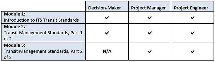
(Extended Text Description: Recommended Prerequisites(s) chart Four rows with four columns. The first column is the Module title column; the corresponding rows in sequence are: Module 1, Module 2, and Module 5. The top tier of rows has three columns: Decision Maker, Project Manager, and Project Engineer. Modules 1 and 2 all have check marks in them, signifying that these modules should be taken as a prerequisite by the Decision Maker, Project Manager, and Project Engineer. Module 5 has "N/A" under the Decision Maker column, signifying that these modules are not applicable for the Decision Maker; and check marks for Project Manager and Project Engineer.)
Slide 10:
Curriculum Path (Decision-Maker)
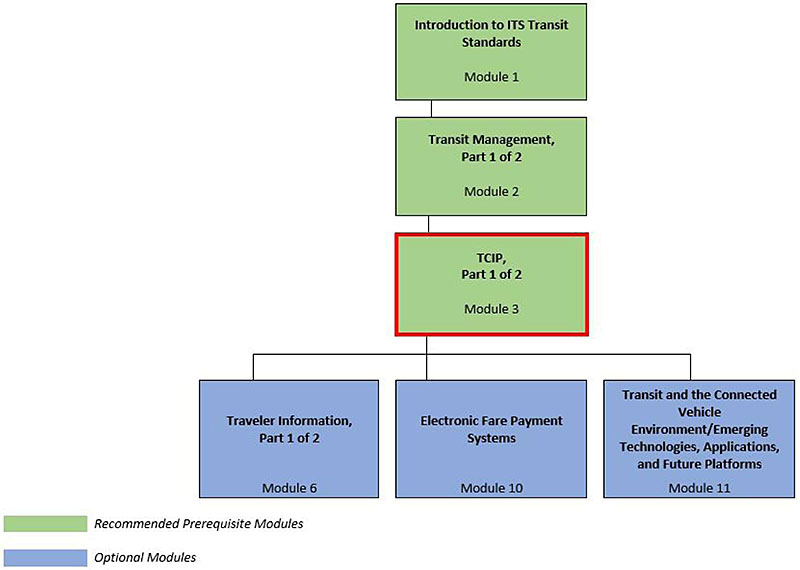
(Extended Text Description: Curriculum Path for Decision Maker A graphical illustration indicating the sequence of training modules and where this module fits in. Each module is represented by a box with the name of the module in it and a flow chart showing the logical flow of the modules with the current module boxed in red. The first three boxes are green and aligned horizontally, green signifying "Recommended Pre-requisites." The first box is "Introduction to ITS Transit Standards, Module 1." Below that, connected by a line, is a box with the text "Transit Management, Part 1 of 2." Below that, connected by a line, is a box with the text, "TCIP, Part 1 of 2," which is outlined in red. From here, the lines branch out into three text boxes that are horizontally sequenced and are in blue, signifying "Optional Modules." These three boxes are: "Traveler Information, Part 1 of 2", "Electronic Fare Payment Systems," and "Transit and the Connected Vehicle Environment/Emerging Technologies, Applications, and Future Platforms.")
Slide 11:
Curriculum Path (Project Manager)
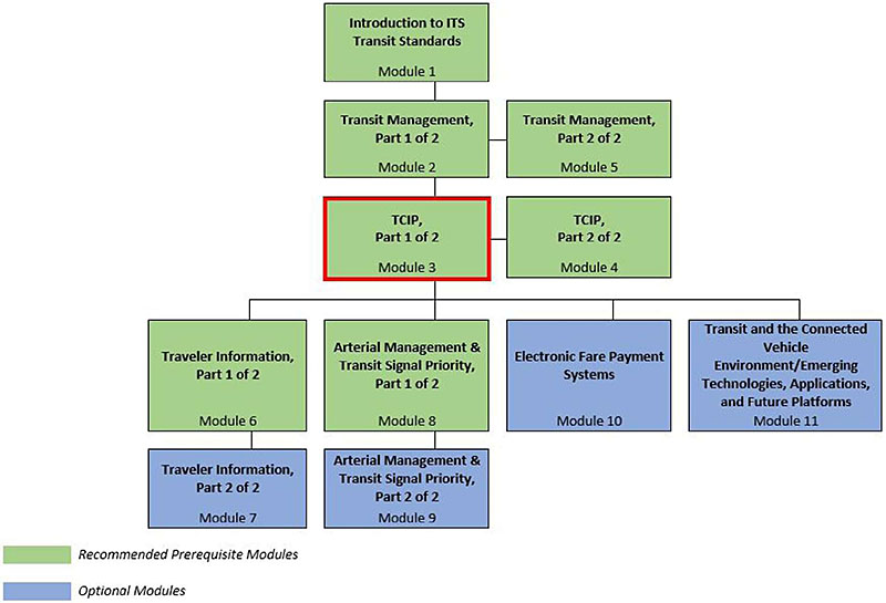
(Extended Text Description: Curriculum Path for Project Manager A graphical illustration indicating the sequence of training modules and where this module fits in. Each module is represented by a box with the name of the module in it and a flow chart showing the logical flow of the modules with the current module boxed in red. The first three horizontally sequenced boxes are green. The first box is "Introduction to ITS Transit Standards, Module 1." Below that, connected by a line, is a box with the text "Transit Management, Part 1 of 2." To the right of this box, is "Transit Management, Part 2 of 2". Below that "Transit Management, Part 1 of 2", connected by a line, is a box with the text, "TCIP, Part 1 of 2," which is outlined in red. To the right of this box, is "TCIP, Part 2 of 2." From here, the lines branch out into four text boxes that are horizontally sequenced. The first two: "Traveler Information, Part 1 of 2" and "Arterial Management & Transit Signal Priority, Part 1 of 2" are green; the last two are "Electronic Fare Payment Systems" and "Transit and the Connected Vehicle Environment/Emerging Technologies, Applications, and Future Platforms." Below "Traveler Information, Part 1 of 2," is the text box "Traveler Information, Part 2 of 2 coded in blue. Below "Arterial Management & Transit Signal Priority, Part 1 of 2", is the text box "Arterial Management & Transit Signal Priority, Part 2 of 2, coded in blue.)
Slide 12:
Curriculum Path (Project Engineer)
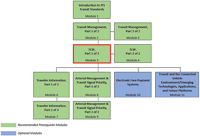
(Extended Text Description: Curriculum Path for Project Engineer A graphical illustration indicating the sequence of training modules and where this module fits in. Each module is represented by a box with the name of the module in it and a flow chart showing the logical flow of the modules with the current module boxed in red. The first three horizontally sequenced boxes are green. The first box is "Introduction to ITS Transit Standards, Module 1." Below that, connected by a line, is a box with the text "Transit Management, Part 1 of 2." To the right of this box, is "Transit Management, Part 2 of 2". Below that "Transit Management, Part 1 of 2", connected by a line, is a box with the text, "TCIP, Part 1 of 2," which is outlined in red. To the right of this box, is "TCIP, Part 2 of 2." From here, the lines branch out into four text boxes that are horizontally sequenced. The first two: "Traveler Information, Part 1 of 2" and "Arterial Management &Transit Signal Priority, Part 1 of 2" are green; the last two are "Electronic Fare Payment Systems" and "Transit and the Connected Vehicle Environment/Emerging Technologies, Applications, and Future Platforms." Below "Traveler Information, Part 1 of 2," is the text box "Traveler Information, Part 2 of 2 coded in green. Below "Arterial Management & Transit Signal Priority, Part 1 of 2", is the text box "Arterial Management & Transit Signal Priority, Part 2 of 2, coded in green.)
Slide 13:
Learning Objectives
- Describe the purpose and contents of the TCIP standard
- Recognize what is involved in growing traveler information and communication systems from basic systems to regional multi-modal applications
- Explain how TCIP is used to procure and implement transit ITS systems
- Illustrate the need for, and structure of, a transit agency architecture
- Articulate the fundamentals of exchanging information among transit business systems and devices using TCIP building blocks
- Summarize the content of the TCIP standard, tools, and available resources
- Provide examples of who is using TCIP
Slide 14:
Learning Objective #1: Describe the Purpose and Contents of the TCIP Standard
- Requirements to use standards
- History and development of TCIP
- Overview of TCIP volumes 1 through 4
- Normative and non-normative content
Slide 15:
Learning Objective #1
Requirements to Use Standards
- Over the past ten years, the U.S. transit industry has spent 18 billion dollars on ITS including communications, fare revenue collection, and information systems
- ITS Standards are voluntary within the industry—they are not required by law, but they may be required by policy within your organization
- ITS Standards are consensus-based—they are developed by working groups of industry experts who ballot the standard
- ITS Standards are open and are not proprietary—they can be used by all
- ITS Standards are the "nuts and bolts" connecting transit management systems
Slide 16:
Learning Objective #1
TCIP* - Transit Communications Interface Profiles
- TCIP is the ITS standard for exchanging information among transit ITS systems and components
- Published by the American Public Transportation Association (APTA)
- Difference between a "protocol" and a "profile" for data exchange—a protocol contains rules and a profile can contain both rules and content
- TCIP references other ITS standards and definitions. This helps to ensure: "-a functional system (by adopting proven standards), and -cross-discipline consistency, helping to simplify integration with non-transit systems"
Slide 17:
Learning Objective #1
Purpose of the TCIP Standard
- Defines standardized interfaces for the exchange of information (data) among transit business systems, subsystems, components, and devices primarily for intra-agency use
- However, TCIP allows transit agencies to comply with Federal requirements to implement regional architectures because it provides a standard to exchange data with other transportation agencies
- Other data exchange standards and protocols such as Google’s GTFS may be used to communicate information to the public, but they do not incorporate many of the data needed to manage a transit system such as operator ID or vehicle mechanical health data
Slide 18:
Learning Objective #1
History of the TCIP Standard
- The primary transit component of the US DOT ITS Standards Initiative; TCIP’s development was funded by USDOT
- Originally developed by the program, National Transportation Communications for Intelligent Transportation System (ITS) Protocol (NTCIP), TCIP was transferred to APTA in 2001
- APTA added dialogs, file transfers, the TCIP Model Architecture, a Concept of Operations, and Transit Signal Priority
- TCIP was balloted* and approved as an APTA Standard in 2006; "Balloting" of the TCIP standard is done by technical working groups (TWG’s) of stakeholder entities (primarily transit agencies, vendors, and consultants). The standard is considered approved when consensus is achieved by 75% of a representative sample of the voting entities
- Current version is APTA TCIP-S-001 4.0*
*Except the Fare Collection Business Area
Slide 19:
Learning Objective #1
TCIP Standard - Documents
TCIP has been published in four volumes.
- Volume I contains an introduction and overview of the standard
- Volume I also contains concepts of operations for ten business process areas found in most transit agencies
- It also provides guidance on conformance and procurement
Slide 20:
Learning Objective# 1
TCIP Standard - Documents
-
TCIP presents much more information than a set of rules typically included in a standard. It includes "profiles" which are the actual building blocks to exchange information between business systems
- Volume II contains these building blocks
-
TCIP uses extensible markup language (XML) to provide a widely-known and supportable data exchange format between business systems, but allows for other transfer syntaxes to be used
- Volume III contains the XML schema
Slide 21:
Learning Objective #1
TCIP Standard - Documents
- Volume IV contains six technical annexes (F-K). Only four are used at this time
-
Annex K includes sample procurement documents for TCIP:
- Profile Requirements List (PRL) Mechanism for conveying an agency’s TCIP requirements to a developer
- Profile Implementation Conformance Statement (PICS) Developer provides, which describes their product as part of the proposal submittal
Slide 22:
Learning Objective #1
Normative and Non-Normative Content
- Normative content is defined as that which has been balloted and is used to implement the standard
-
Non-normative material has not been balloted and is included to explain:
- How TCIP may be used by transit agencies and product developers;
- To provide context for the normative portions of the standard; and/or
- To contain technical material that has been developed, but is not yet deemed mature enough for balloting and implementation.
- The TCIP Task Force, responsible for TCIP developments, has determined that the Fare Collection Business Area is not yet mature enough for balloting and/or implementation
Slide 23:

Slide 24:
Learning Objective #1
What is the purpose of the TCIP standard?
Answer Choices
- Ensure that all transit agencies conform to the same requirements
- Federal requirement on uniformity for all procurements
- Exchange information for transit ITS systems and components
- TCIP is the only standard allowed for transit ITS systems
Slide 25:
Learning Objective #1
Review of Answers
 a) Ensure that all transit agencies conform to same requirements
Incorrect. Agencies can develop their own requirements to meet their needs.
b) Federal requirement on uniformity for all procurements
Incorrect. TCIP use is voluntary. It is not required by the Federal government.
 c) Exchange information for transit ITS systems and components
Correct! TCIP was developed specifically to meet the needs of the transit industry.
d) TCIP is the only standard allowed for transit ITS systems
Incorrect. TCIP is only one of a number of standards that can be used.
Slide 26:
Learning Objective #1
What is the role of balloting in developing a standard?
Answer Choices
- To elect members to standards bodies
- Ensure that a consensus has been achieved on the standard
- Transit agencies’ majority vote is needed to create a standard
- Ensures that Federal reps agree to require the standard
Slide 27:
Learning Objective #1
Review of Answers
a) To elect members to standards bodies
Incorrect. Standards bodies are comprised of industry volunteers.
b) Ensure that a consensus has been achieved on the standard
Correct! Industry working groups use balloting to develop standards.
c) Transit agencies’ majority vote is needed to create a standard
Incorrect. Standards are created by industry groups with a variety of stakeholders.
d) Ensures that Federal reps agree to require the standard
Incorrect. The Federal government does not require ITS standards by law.
Slide 28:
Summary of Learning Objective #1
Describe the Purpose and Contents of the TCIP Standards
- Requirements to use standard
- History and development of TCIP
- Overview of TCIP volumes 1 through 4
- Normative and non-normative content
Slide 29:
Learning Objective #2: Recognize What is involved in Growing Traveler Information and Communication Systems from Basic Systems to Regional Multi-Modal Applications
- Planning for communication systems
- Legacy systems, technological change, and obsolescence
Slide 30:
Learning Objective #2
Planning for Communication Systems
Communications are Fundamental to Transit Management
-
Transit management systems need to accommodate increased data collection and distribution for:
- Large vehicle fleets over significant distances
- Facilities at multiple locations
- Staff operating in the field
- Customers spread over a region
-
Systems planning must include the need to:
- Add capabilities over time
- Replace systems that can no longer be supported
- Interchange information seamlessly and flawlessly
Slide 31:
Learning Objective #2
Legacy Systems, Technological Change, and Obsolescence
- Transit vehicle lifecycles range from 12 to 30 years or more
- Computer technology becomes obsolete in 18 to 24 months
- Replacement parts become more difficult to replace over time
- Operating systems and storage media can be phased out and not supported by vendors
- Existing systems may be incapable of accommodating new software system requirements
- Expect to replace components and systems several times during the life of a bus or rail vehicle
- Expect to replace management systems over time as well
Slide 32:

Slide 33:
Learning Objective #2
Which factor is most likely to lead to changes in communication systems?
Answer Choices
- New technology becomes available
- Transit systems expand into new modes
- New management requirements increase information demand
- New transit vehicles require new radios
Slide 34:
Learning Objective #2
Review of Answers
a) New technology becomes available
Incorrect. The availability of new technology does not mean your existing system will not continue to meet your needs.
b) Transit systems expand into new modes
Incorrect. Transit systems usually can add new vehicles and facilities without fundamental changes to their communication systems.
c) New management requirements increase information demand
Correct! Transit managers are seeking new kinds of information and more data to better manage their systems.
d) New transit vehicles require new radios
Incorrect. New vehicles may be configured to work with existing radios.
Slide 35:
Summary of Learning Objective #2
Recognize What is Involved in Growing Traveler Information and Communication Systems from Basic Systems to Regional Multi-Modal Applications
-
Planning for communication systems
- Communications are fundamental to transit management
- Systems planning must include the need to add capabilities over time
-
Legacy systems, technological change, and obsolescence
- Systems that can no longer be supported must be replaced over time
- Information must be exchanged seamlessly and flawlessly
Slide 36:
Learning Objective #3: Explain How TCIP is Used to Procure and Implement Transit ITS Systems
- Procurement and implementation of transit ITS components
- Using TCIP to facilitate competitive procurements
- Integrating systems using TCIP
Slide 37:
Learning Objective #3
Procurement and Implementation of Transit ITS Components
ITS Technology Applications
-
Transit ITS projects are usually implemented incrementally in an agency and often through separate procurements
- For example, an agency may purchase a CAD/AVL in year 1 and a multimedia traveler information system in year 5
- Integration issues arise when these separately procured systems need to exchange data in order to maximize benefits
- If agency staff do not have the capacity to define interfaces, experienced outside consultants can help prepare TCIP procurement documents that will enable competitive procurements and systems integration
Slide 38:
Learning Objective #3
Procurement and Implementation of Transit ITS Components
TCIP Can Help Overcome the Following Technical Challenges
- Exchanging information with subsystems (within an agency and between agencies)
- Integration with legacy systems
- Defining requirements for connections between a subsystem being procured and future subsystems
- Accommodating future system growth
Slide 39:
Learning Objective #3
Procurement and Implementation of Transit ITS Components
TCIP Can Help Overcome the Following Technical Challenges (cont.)
- Difficult to use multiple vendors, causing agencies to lose flexibility and control
- Hardware obsolescence
- Distribution of transit data to third party developers
- Procurement lag
Slide 40:
Learning Objective #3
Using TCIP to Facilitate Competitive Procurements
- TCIP does so by providing a non-proprietary standard, allowing the transit agency to go beyond a single vendor when looking to upgrade or add to an existing system
- TCIP allows the transit agency to select sub-systems that best fulfill its needs (given the resources available), rather than limiting selections only to those that can be integrated with the proprietary standards and interfaces used in an existing system
Slide 41:
Learning Objective #3
Using TCIP to Facilitate Competitive Procurements
TCIP Standard Approach
-
Recognizes each agency operates differently
- TCIP provides a large variety of information exchanges that agencies can use on an a-la-carte basis according to their needs
-
TCIP is not intended to be adopted as a whole or all at once
- Agencies can purchase TCIP compliant business systems, vehicles, devices, and equipment gradually over time
- Enables agencies to maintain legacy systems
Slide 42:
Learning Objective #3
Using TCIP to Facilitate Competitive Procurements
TCIP Standard Approach
-
Minimizes impact on developers/vendors
- TCIP does not specify interactions within the components
- TCIP does provide standard formats to facilitate the exchange of information
- Does not limit an agency’s communication architecture
Slide 43:
Learning Objective #3
Using TCIP to Facilitate Competitive Procurements
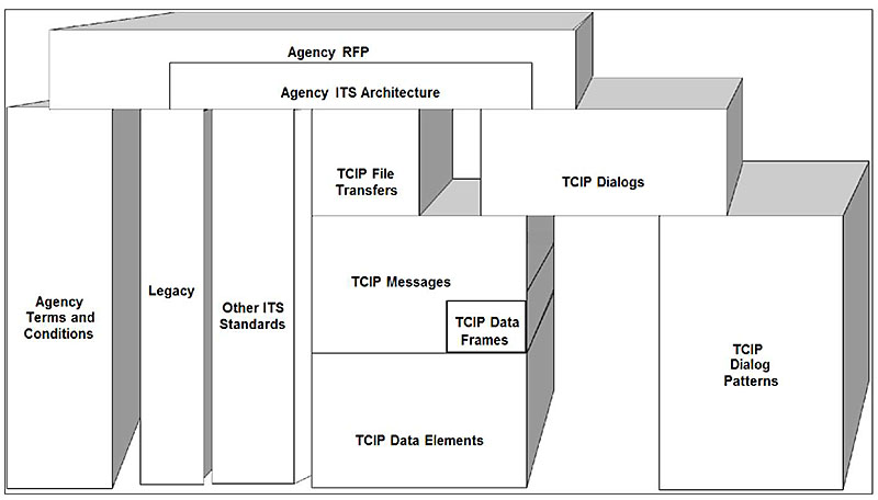
(Extended Text Description: Using TCIP to facilitate competitive procurements This graphic illustrates how TCIP is used in agency procurements for ITS systems. TCIP comprises building blocks at several levels in conjunction with other ITS standards. It shows diagrammatically how TCIP and other requirements fit together within the framework of a Request for Proposal (RFP) which is the common procurement document used to solicit bids from contractors to supply ITS products. The Agency RFP is the top block in the graphic, and includes a block representing the Agency ITS Architecture. This is supported by blocks on the left, which include agency terms and conditions, systems and other ITS standards in use provide context for the procurement. On the right, TCIP building blocks create a specification for the actual information exchanges the agency wants to incorporate into the procurement to ensure that the required systems will be interoperable.)
This graphic illustrates how TCIP is used in agency procurements for ITS systems. TCIP comprises building blocks at several levels in conjunction with other ITS standards.
Slide 44:
Learning Objective #3
Integrating Systems using TCIP
TCIP Model for Data Exchange
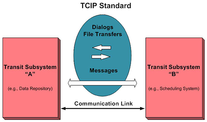
(Extended Text Description: Integrating systems using TCIP This figure illustrates the TCIP model for data exchange. Transit subsystems are represented by blocks on the right and on the left. Between the blocks arrows represent the flow of data between them over an arrow representing the communications link. TCIP dialogs and file transfers are represented by an oval sitting above the communications link showing messages encoded using TCIP exchange profiles.)
TCIP standard enables transit subsystems "A" and "B" to exchange information using TCIP exchange protocols.
Slide 45:

Slide 46:
Learning Objective #3
Which is a key risk in transit ITS procurements?
Answer Choices
- Separately procured systems won’t communicate
- Transit agencies may be overcharged for ITS systems
- Legacy systems do not have backups
- Standards are not available to integrate systems
Slide 47:
Learning Objective #3
Review of Answers
a) Separately procured systems won’t communicate
Correct! Without use of common standards, systems developed by different vendors may not be able to communicate.
b) Transit agencies may be overcharged for ITS systems
Incorrect. Transit agencies can use low price as a way to evaluate bids to avoid overcharging.
c) Legacy systems do not have backups
Incorrect. A legacy system is typically defined as one that is outdated, but it may include backup features.
d) Standards are not available to integrate systems
Incorrect. There are a number of standards that may be used to integrate systems, including TCIP.
Slide 48:
Learning Objective #3
Which is a benefit of using TCIP in transit ITS procurements?
Answer Choices
- Standardize internal components of a vendor’s ITS system
- Lower initial procurement costs
- Allow multiple vendors to compete
- Expand the bandwidth for communications between systems
Slide 49:
Learning Objective #3
Review of Answers
a) Standardize internal components of a vendor’s ITS system
Incorrect. TCIP is intended to standardize only the interfaces between systems.
b) Lower initial procurement costs
Incorrect. In the long run, TCIP may help reduce costs, but there is no guarantee.
c) Allow multiple vendors to compete
Correct! TCIP is intended to allow many vendors to offer systems that can be integrated.
d) Expand the bandwidth for communications between systems
Incorrect. Bandwidth is communication system property. It is unaffected by TCIP.
Slide 50:
Summary of Learning Objective #3
Explain How TCIP is Used to Procure and Implement Transit ITS Systems
- TCIP is used to facilitate competitive procurements when procuring and implementing transit ITS systems by providing a non-proprietary standard, allowing the transit agency to go beyond a single vendor
- TCIP allows the transit agency to select sub-systems that best fulfill its needs (given the resources available), rather than limiting selections only to those that can be integrated with the proprietary standards and interfaces used in an existing system
- TCIP allows each agency to select those interfaces and capabilities within each interface to reflect that particular agency’s needs. TCIP is intended to operate alongside legacy interfaces, even over the same communications media and networks
Slide 51:
Learning Objective #4: Illustrate the Need for, and Structure of, a Transit Agency Architecture
- Capital and project planning for transit ITS
- Linkage of transit agency architecture to national ITS architecture and regional architectures
- Business areas and concepts of operations
- Diagramming an agency architecture
- Case study - development of a transit agency architecture
Slide 52:
Learning Objective #4
Capital and Project Planning for Transit ITS
- Transit ITS system acquisitions are usually included as projects in the agency’s capital program and budget
- Projects may be implemented in phases
- The overall planning framework for an ITS project is called an architecture
- The architecture explains how all systems are integrated and phased over time
Slide 53:
Learning Objective #4
Relationships Between ITS Architectures
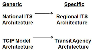
(Extended Text Description: Relationships Between ITS Architectures - On the left, the National ITS Architecture, the generic starting point for a Regional ITS Architecture – Defines all the things a country "might" want to do. This points to the Regional ITS Architecture, on the right, which represents what organizations in a particular region "actually" want to do (an adaptation of the National ITS Architecture). TCIP Model Architecture on the left, is the generic starting point for a Transit Agency ITS Architecture – Defines a lot of things an agency "might" want to do. IT points to the Transit Agency ITS Architecture on the right, which is what an agency "actually" wants to do.)
Slide 54:
Learning Objective #4
What is the TCIP Model Architecture?
- Generic illustration of ITS subsystems and interfaces that a transit agency might employ
- Organized in a similar fashion to the National ITS Architecture (NIA), showing how components are connected using communications links
- Not all agencies will have all components, but all agencies will have some components
- Where equivalents exist, TCIP Annex G maps TCIP Model Architecture Logical Entities to the NIA Process specifications and maps TCIP Dialogs to the NIA data flows
Slide 55:
Learning Objective #4
TCIP Model Architecture
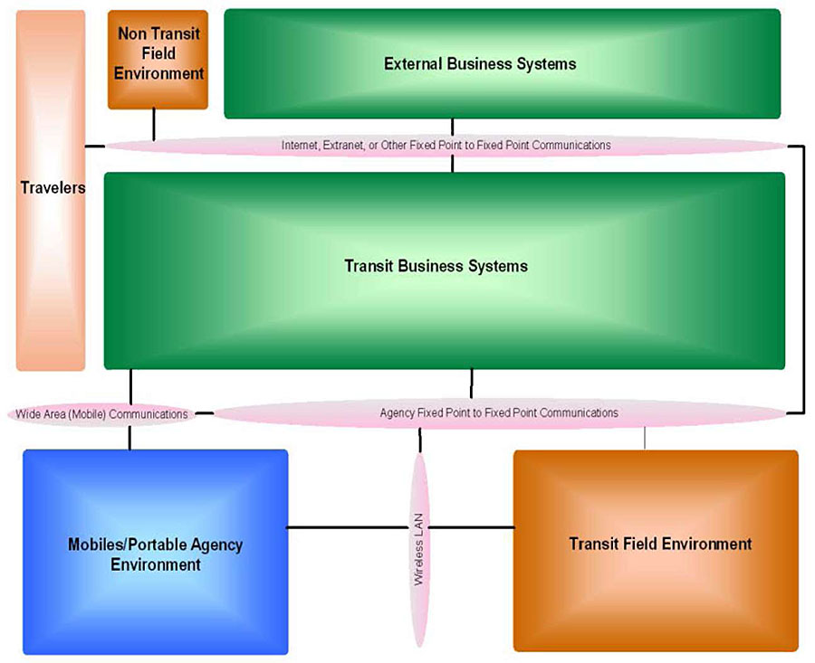
(Extended Text Description: TCIP Model Architecture. The graphic on this slide illustrates the TCIP Model Architecture with various areas where subsystems are located and the communication links between subsystems. At the top is a box that includes External Business Systems. Immediately below that is a box that includes Transit Business Systems – These areas indicate systems that are located in an office and don’t move around (e.g., Banks, Data Repositories, Transit Security, CAD/AVL). Below and to the right of the Transit Business Systems box is a box representing Transit Field Environment – This area indicates systems that are not in an office, but they don’t move around either (e.g., bus stop, station, TVM, kiosk). Above and to the left of the Transit Business Systems box is a box for Non-Transit Field Environment – This area indicates systems that are not in an office, but they don’t move around either AND they are not related to transit (specifically) (e.g., traffic lights). To the left of the Transit Business Systems box is a box representing the Travelers Below and to the left of the Transit Business Systems box which includes Mobiles/Portable Agency Environment – This area indicates systems that move (e.g., vehicles). Between each box is a narrow oval, like a sausage, that depicts the communications links among the various types of systems, including fixed-point communications between stationary elements and wireless communications to elements that move.)
Slide 56:
Learning Objective #4
Generic Transit Agency Architecture
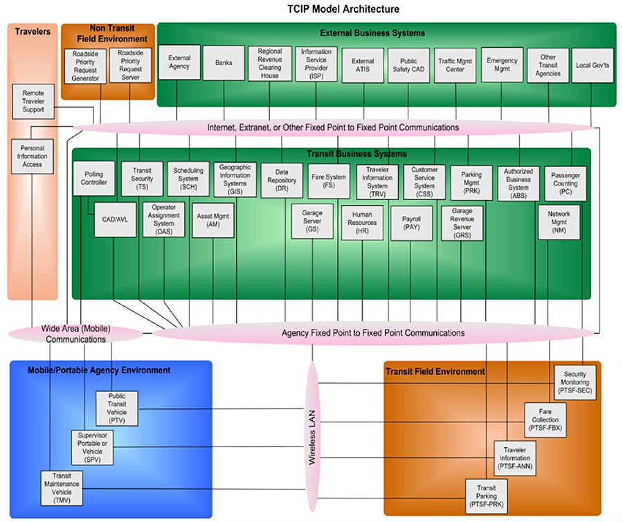
(Extended Text Description: Generic Transit Agency Architecture. Relevant author’s notes: This diagram uses the basic areas described in slide 55, for the TCIP Model Architecture and provides more detail. It shows within each box a series of smaller boxes illustrating the plethora of business systems that could be included. For illustration only.)
Slide 57:
Learning Objective #4
What is a Transit Agency ITS Architecture?
- Modeled after the TCIP Model Architecture
- Specific to a transit agency
- Captures the agency’s near- and long-term plans for technology implementation
- Illustrates an agency’s legacy and planned systems, interfaces, communication networks, external systems, and physical components
Slide 58:
Learning Objective #4
Benefits of a Transit Agency ITS Architecture
- Provides a framework for interdepartmental ITS planning and coordination
- A visual representation of the plan and vision for ITS development within the agency
- Depicts internal and external interfaces between subsystems
- Electronic model of agency’s business
Slide 59:
Learning Objective #4
Transit Core Business Processes
- Security and Incident Management Process
- Public Transit Vehicle (PTV) Operations Process
- Revenue and Fare Collection Process
- Scheduling Process
- Personnel and Work Assignment Management Process
- Asset Management Process
- Customer Information Process
- Data Repository Operations Process
- Spatial Data Management Process
- Transit Signal Priority Process
Slide 60:
Learning Objective #4
TCIP Concept of Operations
- Describes the 10 Transit Core Business Processes
- Explains how TCIP can be used to facilitate communication among transit applications
- Provides "typical" agency implementations of TCIP - does not include all possible processes
- Examine how your agency’s business processes relate to the TCIP Core Business Processes
- Additional transit business processes may be added in the future, e.g., paratransit
Slide 61:
Learning Objective #4
Example - Scheduling Process
- Purpose is to develop transit schedule products and distribute those products to a data repository or other business systems
-
Sub-processes within the scheduling process:
-
Gather data for schedule writing
- Think - "Where does the data reside?"
-
Develop scheduling products
- Schedule writing, block-building, and run cutting
- Distribute scheduling products
-
Gather data for schedule writing
Slide 62:
Learning Objective #4
TCIP Standard Volume I Section 5.5.4.3 -Distributing Scheduling Products
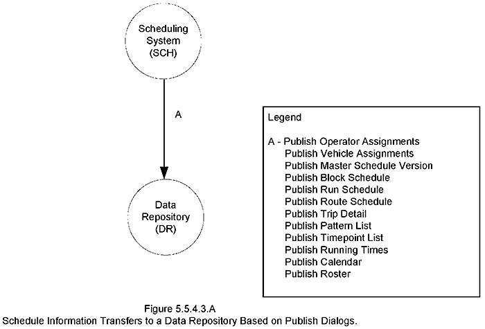
(Extended Text Description: TCIP Standard Volume I Section 5.5.4.3 Distributing Scheduling Products. A Schedule Information Transfers to a Data Repository Based on Publish Dialogs. This figure is reproduced from TCIP Volume I. It shows a circle at the top representing a scheduling system with an arrow pointing down to a circle representing a Data Repository. The arrow represents data flow. A legend on the side shows the various types of data being published, including: Operator Assignments, Vehicle Assignments, Master Schedule Version, Block Schedule, Run Schedule, Route Schedule, Trip Detail, Pattern List, Timepoint List, Running Times, Calendar, and Roster.)
Slide 63:
Learning Objective #4
TCIP Standard Volume I Section 5.5.4.3 -
Distributing Scheduling Products (cont.)
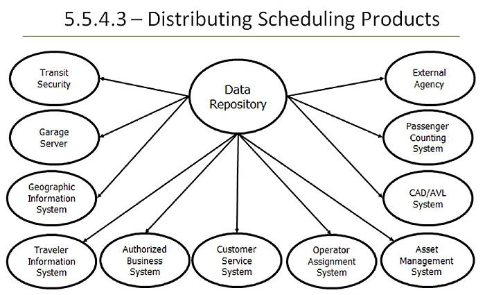
(Extended Text Description: TCIP Standard Volume I Section 5.5.4.3 Distributing Scheduling Products (continued) – This slide shows an oval in the center representing the data repository connected by arrows denoting data flows to eleven other ovals representing various business systems that need to receive scheduling products, including: Transit Security System, Garage Server, Geographic Information System, Traveler Information System, Customer Service System, Operator Assignment System, External Agency, Passenger Counting System, CAD/AVL System, Asset Management System, and other Authorized Business System.)
Slide 64:

Slide 65:
Learning Objective #4
Diagramming an Agency Architecture
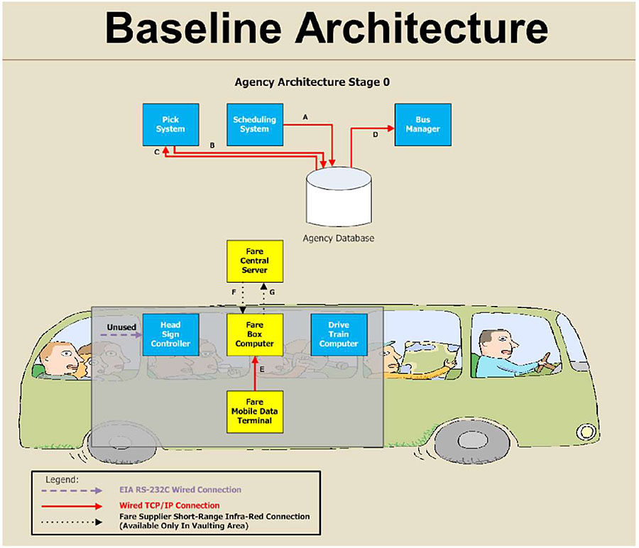
(Extended Text Description: Diagramming an agency architecture This figure illustrates an agency architecture diagram showing a base year configuration of systems on the bus and in the management center. Boxes represent various systems and lines with arrows show the data flows among the systems. A pick system*, a scheduling system and a bus manager system all interface with the agency database using TCP/IP internet type connections. On the bus, a head sign controller and the drive train computers operate independently. A Fare Mobile Data Terminal on the bus has a wired connection to the farebox computer. The farebox computer can exchange data with a central fare server at the garage using an infra-red connection. The agency has plans to add additional functionality in year 3 of their ITS capital program and how the architecture changes will be seen in the next slide. *A "pick" system is one that is used for drivers to choose work assignments. Some agencies refer to these systems as "sign-up" systems or use other names.)
Slide 66:
Learning Objective #4
Diagramming an Agency Architecture (cont.)
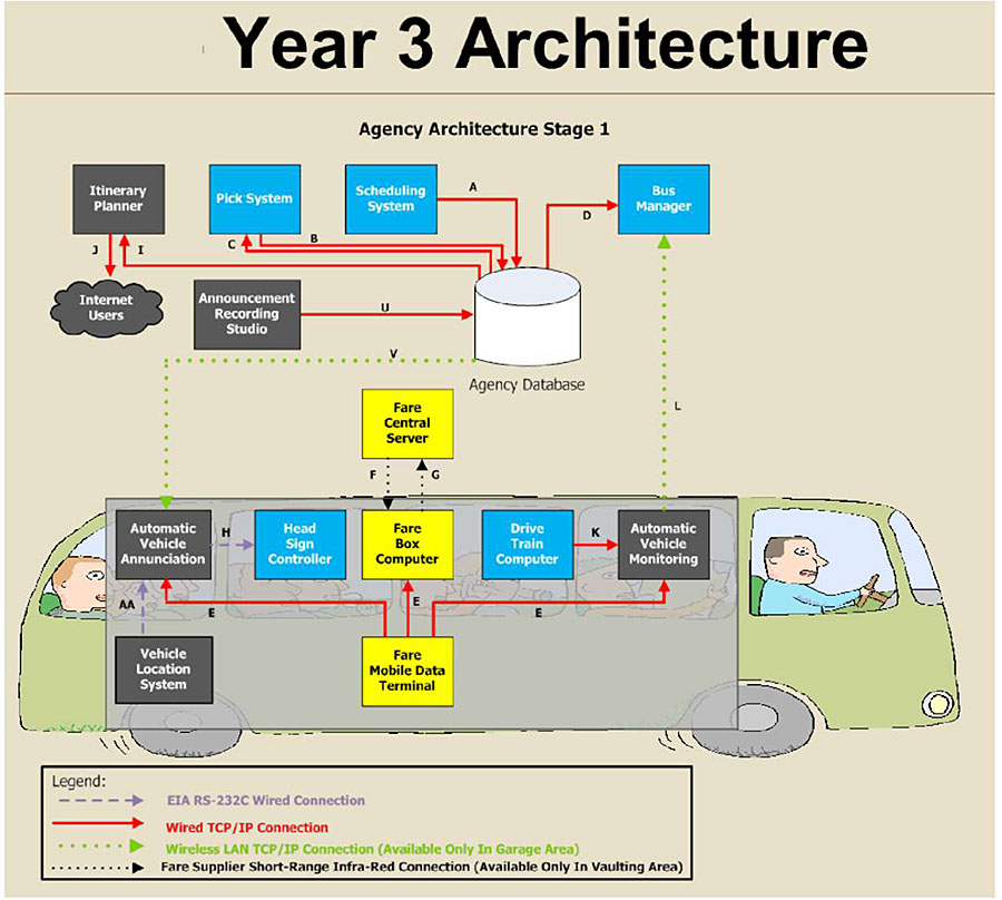
(Extended Text Description: Diagramming an agency architecture (continued) Year 3 Architecture - This slide is to be compared with the previous one to show the second stage of implementation for the agency’s ITS architecture. Boxes represent various systems and lines with arrows show the data flows among the systems. In year 3, the agency intends to add: an itinerary planner that directly feeds customers via the internet, an announcement recording studio system, an automatic vehicle stop annunciation system, a vehicle location system, and an automatic vehicle health monitoring system. These systems will require more integration with other systems and the architecture has added lines representing additional data communication flows. Data flows between the bus and the management center now will use wireless local area networks.)
Slide 67:
Learning Objective #4
Diagramming an Agency Architecture (cont.)
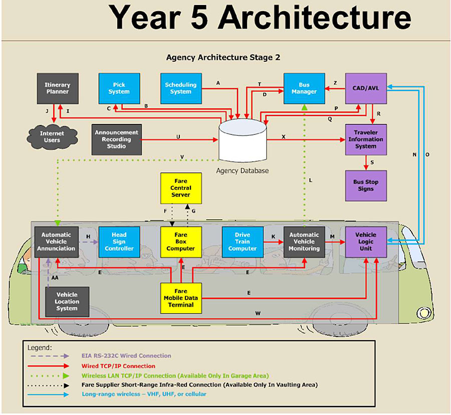
(Extended Text Description: Diagramming an agency architecture (continued) - Year 5 Architecture The year 5 architecture adds long range wireless data communications between the vehicle and the management center. Additional boxes representing systems and lines representing data flows are added. On board the bus, the vehicle location system, which had been used in year 3 only to drive an automatic stop annunciator system, now has its location data sent via the stop annunciator to the vehicle logic unit, which allows the bus location to be transmitted back to a computer aided dispatch/automatic vehicle location (CAD/AVL) system. The CAD/AVL system now sends data to a Traveler Information System which in turn feeds data to Electronic Bus Stop Sign Displays.)
Slide 68:
Learning Objective #4
Architecture Implementation Process
- Define the architecture using block diagrams
- Define the information flows across the interfaces
- Specify the requirements that support the information flows across each interface
- Verify conformance after procurement
Slide 69:

Slide 70:
Learning Objective #4
Which answer best describes the use of an agency architecture to aid in capital and project planning?
Answer Choices
- Shows the buildings needed to house new systems
- Specifies the costs of systems for budgeting
- Must specify how vehicles communicate with control center
- Shows which systems need to interface with other systems
Slide 71:
Learning Objective #4
Review of Answers
a) Shows the buildings needed to house new systems
Incorrect. Architecture in this context applies to systems, not buildings.
b) Specifies the costs of systems for budgeting
Incorrect. The architecture can help budgeting, but it does not include costs.
c) Must specify how vehicles communicate with control center
Incorrect. An architecture could include vehicle-to-base communications, but that is not a requirement. The architecture could include only fixed facilities.
d) Shows which systems need to interface with other systems
Correct! The architecture explains how all systems are integrated and phased over time.
Slide 72:
Learning Objective #4
What are the key elements displayed in an architecture diagram?
Answer Choices
- All transit vehicles and fixed facilities in a system
- All business processes in agency concept of operations
- Only those components that are TCIP compliant
- Selected business systems and data flows
Slide 73:
Learning Objective #4
Review of Answers
a) All transit vehicles and fixed facilities in a system
Incorrect. The architecture should include representations of only those elements that are linked by communications and information flows.
b) All business processes in agency concept of operations
Incorrect. Only those business processes that exchange (or will exchange) information with other business processes need to be included in the architecture.
c) Only those components that are TCIP compliant
Incorrect. The architecture should include all components that exchange information, not just TCIP compliant ones.
d) Selected business systems and data flows
Correct! Architecture diagrams generally show selected systems and components as boxes or circles and data flows by lines.
Slide 74:
Learning Objective #4
Summary of Learning Objective #4
Illustrate the Need for, and Structure of, a Transit Agency Architecture
- The overall planning framework for an ITS project is called an architecture. The architecture explains how all systems are integrated and phased over time
- A transit agency architecture is modeled on the national ITS architecture and can be included in a regional architecture to show interagency data flows
- The model TCIP architecture includes a concept of operations that includes ten common business areas that may be used by most transit agencies
Slide 75:
Learning Objective #4
Summary of Learning Objective #4 (cont.)
Illustrate the Need for, and Structure of, a Transit Agency Architecture
- Diagramming a transit agency architecture uses block diagrams to show sub-systems and lines to show information flows
- The case study shows how an agency architecture can be used to show how systems will be added over time and how systems will be integrated
Slide 76:
Learning Objective #5: Articulate the Fundamentals of Exchanging Information Among Transit Business Systems and Devices Using TCIP Building Blocks
- Batch and real-time information exchanges
- Data elements, data frames, messages and dialogs
Slide 77:
Learning Objective #5
File-Based Transfer
Transfer Data Without the Use of Dialogs in a Non-Real-Time Manner
- Computer application saves data in a file
- File is transferred to another system
-
File is loaded and read by another computer application
- Sometimes involves human interaction
-
This interaction requires an agreed-upon description for the files
- TCIP messages provide this description
Slide 78:
Learning Objective #5
Dialog-Based Transfer
Real-Time Transfer (Machine to Machine) Using Dialogs
Dialogs Specify:
- The operational purpose of the exchange of information
- Dialog pattern
- Messages included in the dialog
- Special conditions/constraints
- Relationships with other dialogs
Slide 79:
Learning Objective #5
Dialog-Based Transfer (cont.)
Real-Time Transfer (Machine to Machine) Using Dialogs
Dialogs do not define:
- How data is stored, translated, and manipulated
- How data is formatted and presented to human users
- How systems/components trigger or initiate dialogs
- Details of the interactions with human users
Slide 80:
Learning Objective #5
Dialog Patterns
The graphic shows the systems exchanging data as grey rectangles. The arrows illustrate the message flows in the dialog in time sequence starting at the top.
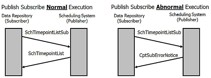
(Extended Text Description: Dialog Patterns - The graphic shows the systems exchanging data as grey rectangles on each side. The system on the left is a data repository which is a subscriber. The system on the right is a Scheduling System, which is a publisher. Arrows between the grey rectangles, like tilted rungs on a ladder, illustrate the message flows in the dialog in time sequence starting at the top. Dialog patterns define a sequence of actions in a generic format that can be reused. This example shows the operation of the Publish Subscribe Dialog Pattern. The subscriber requests information (in this case the Timepoint List) using a Query Message (in this case SchTimepointListSub). In a normal execution, the publisher responds with the requested information (in this case a SchTimepointList message). Depending on the content of the query, there may be a single answer or an ongoing set of answers. An ongoing set of answers is appropriate when the requested information changes on an ongoing basis (e.g., vehicle location). In an abnormal execution, the subscriber requests the information and if the publisher determines the information is unavailable, then the subscriber is not authorized. As a result, the publisher returns an error message (CptSubErrorNotice).)
Slide 81:
Learning Objective #5
TCIP Building Blocks
Hierarchy to Help you Define Data
-
"How" the data is transmitted
- File transfers (non-real time)
- Dialogs (real time; machine to machine)
- Dialog patterns
-
"What" data is transmitted
- Messages
- Data frames
- Data elements
Slide 82:
Learning Objective #5
TCIP Building Blocks (cont.)
This graphic illustrates the distinction between what data is transferred, which is shown below the blue line; and how the data is transferred, which is shown above the blue line.
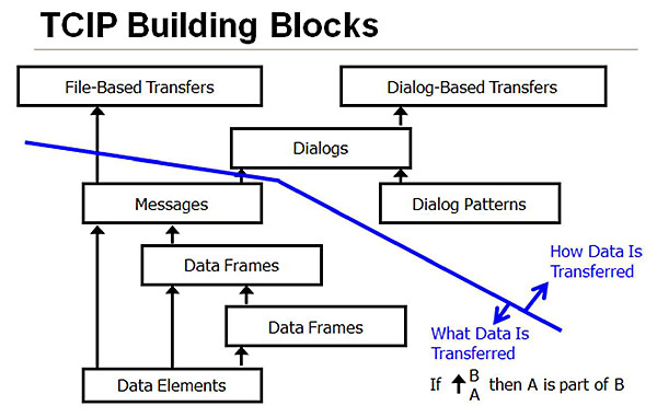
(Extended Text Description: TCIP Building Blocks - This figure shows a series of boxes arranged in a hierarchy below a line. The hierarchy starts with a box at the bottom representing data elements. This box is linked to boxes above it with arrows representing the buildup of higher levels of structure for data. These levels represent data frames and messages. These boxes represent what data is being transferred. The message box just below the line represents "messages" the highest level of the "what" that is being transferred. Above the line are boxes that represent how data is transferred. Messages are linked by arrows crossing the line to a box representing file based transfers and to a box representing dialogs. A box representing dialog patterns feeds into the dialog box. The dialog box in turn feeds a box representing dialog-based transfers.)
Slide 83:
Learning Objective #5
Data Element
An Atomic Piece of Information Related to a Person, Place, Thing or Concept
-
Examples:
- SCH-TimepointID - a timepoint identifier
- SCH-TimepointName - a timepoint name
- LRMS.Latitude - latitude in microdegrees
Slide 84:
Learning Objective #5
Data Frame
Grouping of Data Elements and Other Data Frames to Describe More Complex Concepts
-
The groupings help to organize information to describe or identify objects or concepts in the real world
-
SCHTimepointlden identifies a timepoint
- Contains the data element with its unique alpha-numeric identifier (SCH-TimepointID), and can also contain optional data elements including agency number, and name
-
SCHTimepointlnfo describes a timepoint
- Contains its identifier and location
-
SCHTimepointlden identifies a timepoint
Slide 85:
Learning Objective #5
Message
An Aggregate of Data Elements and Data Frames into a Larger, More Complex Structure
- A complete, understandable, one-way communication that consists of data elements and data frames conveying metadata and information
- For example, SchTimepointList is a message transmitting a list of all stop points
Slide 86:
Learning Objective #5
Dialog
TCIP Includes Eleven Dialog Patterns
- Publication (query, periodic, and event)
- Command-Response
- Report
- Silent alarm
- Load
- Unload
- Voice radio call (operator-initiated and dispatch-initiated)
- Signal control and prioritization
- Blind notification
- Push
- Traveler service request
Slide 87:

Slide 88:
Learning Objective #5
How can TCIP be used to transfer data?
Answer Choices
- Transfer data in files and real-time dialogs
- Only transfer data in real-time dialogs
- Transfer data in publish-subscribe mode
- Transfer data only over the internet
Slide 89:
Learning Objective #5
Review of Answers
a) Transfer data in files and real-time dialogs
Correct! TCIP is intended for both batch file and real-time data transfers.
b) Only transfer data in real-time dialogs
Incorrect. TCIP can be used to transfer data in batch file transfers.
c) Transfer data in publish-subscribe mode
Incorrect. There are eleven different dialog patterns to transfer data in TCIP.
d) Transfer data only over the internet
Incorrect. TCIP is neutral with respect to electronic data communication mode.
Slide 90:
Learning Objective #5
Which statement most accurately characterizes a TCIP dialog?
Answer Choices
- A TCIP dialog is a sequence of data elements
- A TCIP dialog is a digital voice communication pattern
- A TCIP dialog is a structured exchange of messages
- A TCIP dialog is a message with two parts
Slide 91:
Learning Objective #5
Review of Answers
a) A TCIP dialog is a sequence of data elements
Incorrect. A TCIP dialog is a sequence of messages.
b) A TCIP dialog is a digital voice communication pattern
Incorrect. TCIP dialogs are used to transfer data.
c) A TCIP dialog is a structured exchange of messages
Correct! TCIP dialogs typically follow a defined pattern that can be repeated.
d) A TCIP dialog is a message with two parts
Incorrect. A dialog contains messages which may have many parts.
Slide 92:
Learning Objective #5
Summary of Learning Objective #5
Understand the Fundamentals of Exchanging Information among Transit Business Systems and Devices Using TCIP Building Blocks
- TCIP can be used to transfer data through file transfers, in which a file can be transferred from one system to another electronically or on various types of computer media, such as USB drives
- Or, it can be transferred in real time using TCIP messages and dialogs
Slide 93:
Learning Objective #5
Summary of Learning Objective #5 (cont.)
Understand the Fundamentals of Exchanging Information among Transit Business Systems and Devices Using TCIP Building Blocks
-
TCIP is comprised of building blocks including
- Data elements which are "atomic" pieces of data
- Data frames, which are standardized groupings of data elements
- Messages, which are complete one-way communications comprised of data elements and data frames
-
Dialogs, which are structured exchanges of messages that specify:
- An operational purpose
- The dialog pattern to be used
- The messages to be used with the specified dialog pattern
- Any special conditions or constraints associated with the implementation of the specific dialog
Slide 94:
Learning Objective #6: Summarize the Content of the TCIP Standard, Tools, and Available Resources
- Downloads available from APTA
- TCIP tools - Using TIRCE to access TCIP (to be detailed in Module 4: TCIP II)
- Message Builder and Test Console
- Overview of National Transit Institute (NTI) on-site training for TCIP
Slide 95:
Learning Objective #6
TCIP Downloads Available from APTA
All TCIP Products can be downloaded free of charge from: https://www.apta.com/
-
Documents - TCIP Versions contain the standard and non-normative information
- Current
- Baseline
- Working
- Archive
-
Verification - Tools to test TCIP conformance
- TCIP Test Console
-
TIRCE - Tools to access TCIP and develop procurement documents
- TCIP Implementation, Requirements and Capabilities Editor (TIRCE)
Slide 96:
Learning Objective #6
TCIP Support Tool Suite (cont.)
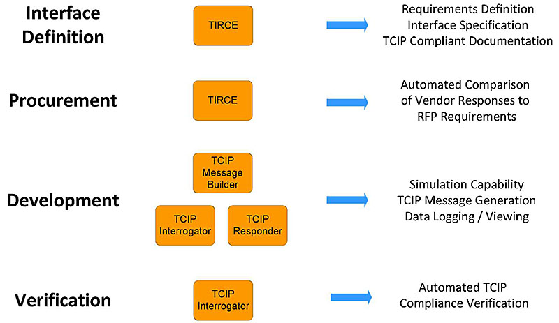
(Extended Text Description: TCIP Support Tools Suite (cont.) This slide shows items in three columns which illustrate the typical sequence in which TCIP tools are used and the purpose of each. Column one shows stages in the process. Column two show boxes labeled with the TCIP tools that are used. Column three shows the capability provided by each tool in the sequence. Starting at the top: "Interface Definition" is accomplished using the tool "TIRCE" which produces "Requirements Definition," Interface Specification, "and TCIP Compliant Documentation." The second stage, "Procurement," is accomplished using the tool "TIRCE" which produces an "Automated Comparison of Vendor Responses to RFP Requirements." The third stage, "Development" uses three TCIP tools, "TCIP Message Builder," TCIP Interrogator," and "TCIP Responder." These tools provide "Simulation Capability," TCIP Message Generation," and Data Logging/Viewing" The fourth stage, "Verification" uses the tool "TCIP Interrogator" which produces an "Automated TCIP Compliance Verification.")
Slide 97:
Learning Objective #6
TIRCE - TCIP Implementation, Requirements and Capabilities Editor
- Guide user through a step-by-step process of converting an agency’s functional requirements into a TCIP compliant specification
-
A top-down systems engineering approach to defining the data exchange interfaces between transit components
- Information that will be exchanged
- Manner in which information is exchanged
Slide 98:
Learning Objective #6
TIRCE Outputs
-
Agency Procurement Specification
- PRL - Profile Requirements List
-
Vendor Product Capabilities Specification
- PICS - Profile Implementation Conformance Statement
-
"Diff" function - A comparison of agency PRL requirements with developer PICS claims of conformance
- Allows an agency to determine if the offered TCIP implemented interface will meet the agency’s requirements.
Slide 99:
Learning Objective #6
TCIP Message Builder
- Enables user to generate XML-encoded TCIP messages
- Messages are used by the TCIP Interrogator and TCIP Server applications
- Load/save/view/edit TCIP messages
Slide 100:
Learning Objective #6
TCIP Interrogator
-
Simulates a TCIP-compliant device
- Client side of interface
- Subscribes to a provider (publisher) of TCIP data
- Establishes a TCIP communications link with a TCIP device under development or test
- Transmits/receives TCIP messages
- View/log TCIP messages
- Automated TCIP message verification
Slide 101:
Learning Objective #6
TCIP Responder
-
Simulates a TCIP-compliant device
- Server side of interface
- Provides TCIP data upon receipt of a subscription request
-
Data is pre-loaded
- Previously created (via TCIP Message Builder) or recorded TCIP messages
Slide 102:
Learning Objective #6
Overview of National Transit Institute (NTI) on-Site Training for TCIP Sponsored by fTa
- NTI offers a two-day hands-on course - Integrating Transit Applications: Defining Data Interfaces Using TCIP
- Agencies can host a course by providing an appropriate venue and coordinating with NTI at https://www.ntionline.com/
- The course is provided free to agency employees but consultants and vendors are charged a fee
- Students must bring a laptop with a compatible Windows operating system
- Students download TIRCE and TCIP tools onto laptops they use during the course and can take with them
Slide 103:

Slide 104:
Learning Objective #6
Why does TCIP include a suite of tools?
Answer Choices
- To fix bugs in the standard
- To develop an agency architecture
- To allow developers to revise and re-ballot the standard
- To develop procurement documents and test compliance
Slide 105:
Learning Objective #6
Review of Answers
a) To fix bugs in the standard
Incorrect. TCIP tools are not used to fix bugs in the standard.
b) To develop an agency architecture
Incorrect. TCIP Volume 1 provides a concept of operations to aid in developing an agency architecture.
c) To allow developers to revise and re-ballot the standard
Incorrect. TCIP tools are not used in developing and balloting the standard.
d) To develop procurement documents and test compliance
Correct! TCIP tools include TIRCE to develop procurement documents (PRL and PICS) and the Message Builder and Test Console to aid in testing TCIP interfaces.
Slide 106:
Learning Objective #6
Summary of Learning Objective #6
Summarize the Content of the TCIP Standard, Tools, and Available Resources
- Downloads available from APTA
- TCIP tools - Using TIRCE to access TCIP (to be detailed in Module 4: TCIP II)
- Message Builder and Test Console
- Overview of National Transit Institute (NTI) on-site training for TCIP
Slide 107:
Learning Objective #7: Who is Using TCIP?
Examples and Real World Applications
-
Current TCIP Projects:
- LYNX (Orlando)
- King County Metro (Seattle)
- New York MTA (NYC)
- AMT (Montreal)
Slide 108:
Learning Objective #7
Who is Using TCIP?
Examples and Real World Applications
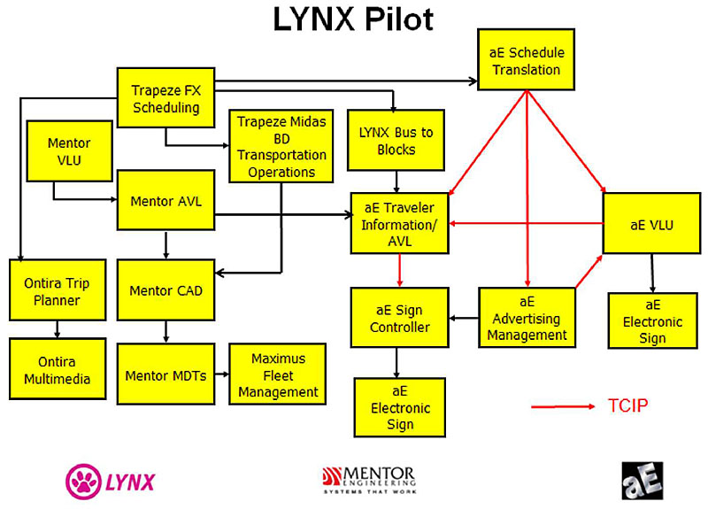
(Extended Text Description: Who is using TCIP? Examples and Real World Applications – Lynx Pilot This slide shows a snapshot of the FUTURE LYNX (Orlando) Agency ITS Architecture. Non-TCIP interfaces are shown by black lines connecting the boxes. TCIP interfaces are shown by red lines. Descriptions for non-generic boxes in the LYNX Architecture Trapeze Scheduling is a Transit Schedule Development Platform. This system provides data to Trapeze BD and to aE Schedule Translation which uses TCIP to interface with aE Traveler Information/AVL, aE Advertising Manager and aE VLU Trapeze BD Transportation Operations provides bid processing, dispatch control, and timekeeping and sends data to Mentor CAD Mentor AVL provides near-real time bus tracking data to Mentor CAD and to aE Traveler Information/AVL Mentor CADD provides computer assisted management of buses while they are en route as well as for initial dispatch. LYNX Bus to Blocks is a LYNX IT Application that manages the daily assignment of buses to blocks (work assignments) which also provides information to aE Traveler Information/AVL Ontira Trip Planner provides customers with address-to-address trip planning by combining a routing algorithm with dynamic mapping and provides data to Ontira Multimedia which provides customers with service information via a variety of communications media (phones, internet, kiosks, etc.).)
Slide 109:
Learning Objective #7
Who is Using TCIP? (cont.)
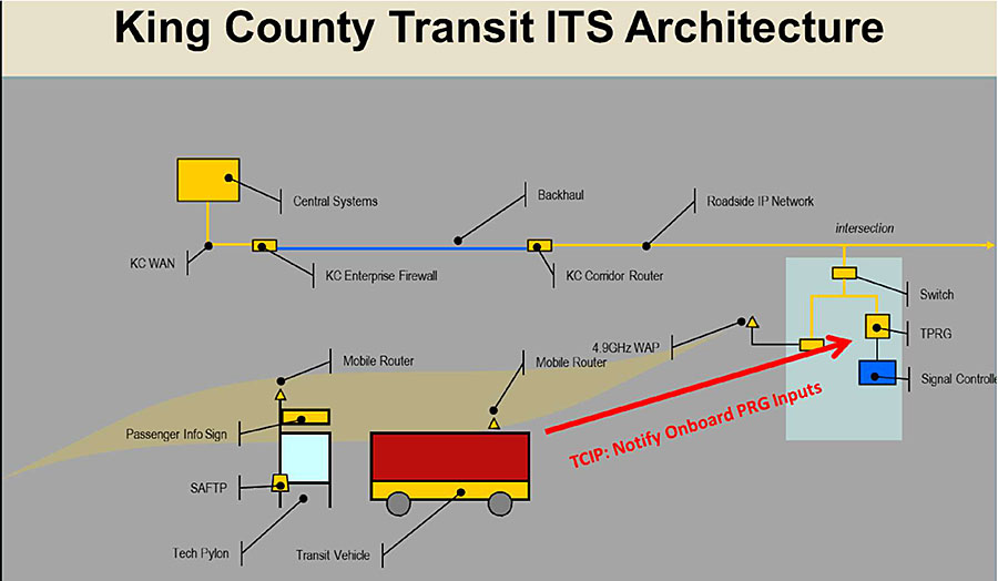
(Extended Text Description: Who is using TCIP? Examples and Real World Applications (cont.) – Author’s relevant notes, for illustration purposes only: King County Transit ITS Architecture This graphic shows the King County Metro architecture for Transit Signal Priority. TCIP will be used to communicate information that supports signal priority requests from buses to the traffic signal control system. The TCIP compliant interface is shown as a red line. The conversation between the Priority Request Generator (PRG) and the Priority Request Server (PRS) uses a different standard.)
Slide 110:
Learning Objective #7
Who is Using TCIP? (cont.)
MTA Bus Time Technology: http://bustime.mta.info/wiki/Main/Technology
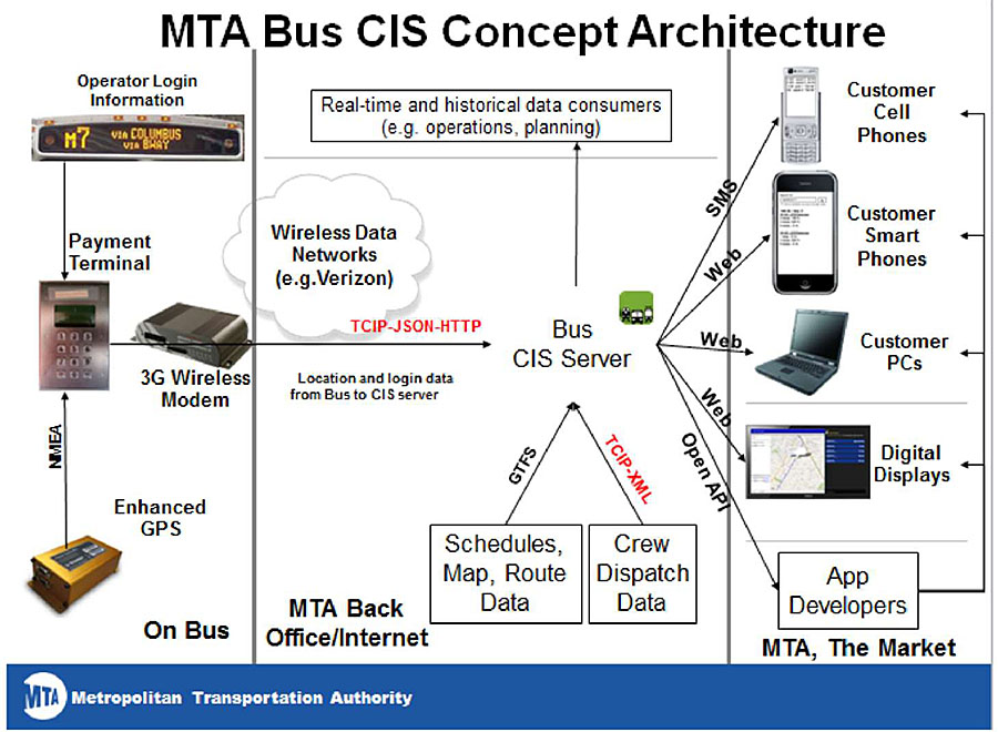
(Extended Text Description: Who is using TCIP? Examples and Real World Applications (cont.) – MTA Bus Time Technology – MTA Bus CIS Concept Architecture. This graphic illustrates the New York MTA’s bus customer information system architecture. TCIP is used in conjunction with other standards to communicate real time bus arrival data every 30 seconds from 5,500 buses to the central server. On the left are shown components on a bus, including the Operator Login Information which is sent to the Payment Terminal. An enhanced GPS unit provides NEMA standard location data to the Payment Terminal which then sends location and login data from the bus to a 3G modem. The Verizon wireless data network sends the data which uses standards including TCIP, JSON and HTTP to the CIS server in the MTA back office. Here, GTFS standard is used to send Schedules, Map and Route Data to the Bus CIS Server. TCIP is used to send crew dispatch data to the Bus CIS Server. The Bus CIS Server uses SMS to send information to customer cell phones, and uses the web to send data to smart phones, customer PCs, and digital displays.)
Slide 111:
Learning Objective #7
Who is Using TCIP? (cont.)
Examples and Real World Applications - AMT Montreal
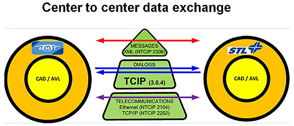
(Extended Text Description: Who is using TCIP? Examples and Real World Applications (cont.) AMT Montreal -This graphic illustrates how Montreal’s Agence Métropolitaine de Transport (AMT) uses TCIP dialogs to exchange data between two different CAD/AVL servers. A CAD/AVL Server for AMT is shown as a circle on the left. This exchanges data over a communications stack depicted as a triangle in the middle. On the right, a circle represents the CAD/AVL server for a sister agency, STL. The triangle segments in the middle illustrate the communication layers involved the exchange. Ethernet protocols are the bottom layer. TCIP is the next layer which is used to specify the dialogs. The messages in the dialogs are encoded in XML using the TCIP schema shown as the top layer.)
Slide 112:

Slide 113:
Learning Objective #7
In what types of applications could my agency use TCIP?
Answer Choices
- Control center to control center
- Provide data to support Transit Signal Priority requests
- Communicate real-time bus arrival information
- Communicate between vehicles and base
- All of the above
Slide 114:
Learning Objective #7
a) Control center to control center
Montreal is using TCIP for center to center.
b) Provide data to support Transit Signal Priority requests
King County is using TCIP to supplement transit signal priority request generation.
c) Communicate real time bus arrival information
MTA NYCT is using TCIP for real time arrival information.
d) Communicate between vehicles and base
LYNX will use TCIP to connect on-board VLU to passenger information system.
e) All of the above
Correct! TCIP has been, and can be used for all of the applications in the question. Can you think of other interfaces for which using TCIP would benefit your agency?
Slide 115:
Review of Learning Objective #7
Who is Using TCIP? Examples and Real World Applications
-
TCIP is being used by a number of agencies in different ways. Four examples are shown:
- Lynx in Orlando FL is using TCIP to provide real-time traveler information and to drive electronic display signs including advertising
- King County, WA is using TCIP to communicate information to support generation of Transit Signal Priority (TSP) requests to a main server
- MTA New York City Transit is using TCIP to communicate realtime bus arrival information every 30 seconds from 5,500 buses
- AMT Montreal is using TCIP dialogs to communicate between two different Computer Aided Dispatch/Automatic Vehicle Locator (CAD/AVL) systems in two different control centers
Slide 116:
What We Have Learned
- Transit Communications Interface Profiles (TCIP) is the ITS standard for exchanging information among transit ITS systems and components.
- TCIP facilitates competitive procurements by providing a non-proprietary standard, allowing the transit agency to go beyond a single vendor when looking to upgrade or add to an existing system.
- An agency ITS architecture provides a framework for interdepartmental ITS planning and coordination. It is a visual representation of the plan and vision for ITS development within the agency.
Slide 117:
What We Have Learned (cont.)
- The TCIP concept of operations describes ten Transit Core Business Processes and explains how TCIP can be used to facilitate communication among transit applications.
- TCIP building blocks consist of data element, data frames, messages, and dialogs.
- TCIP includes a suite of tools including the TCIP Implementation, Requirements and Capabilities Editor (TIRCE) to develop procurement documents (PRL and PICS) and the Message Builder and Test Console to aid in testing TCIP interfaces.
Slide 118:
Resources
- "NTI Instructor Materials: Integrating Transit Applications: Defining Data Interfaces Using TCIP," Power Point Presentation, NTI, February, 2012
- J. Fayos, Draft "NTI Instructor Materials: Integrating Transit Applications: Defining Data Interfaces Using TCIP," NTI, August, 2013
- Figure 9.2 "TCIP Provides the Building Blocks for Agency ITS architectures and RFPs," APTA TCIP-S-001 4.0.0 Volume I, p. 328.
- Concept of operations - Wikipedia, the free encyclopedia , accessed July 12, 2014 https://www.google.com/search?q=definition+concept+of+operations&rlz=1C1LDJZ_enUS499US518&oq=definition+concept+of+&aqs=chrome.1.69i57j0l5.7685j0j8&sourceid=chr ome&es sm=122&ie=UTF-8
- ITS PCB T3 Webinars on ITS Transit Standards t3_archives.aspx
- "Integrating Transit Applications: Defining Data Interface Requirements Using TCIP -Participant Workbook," accessed September 22, 2014 https://drive.google.com/file/d/0B15yEPgHsRUAakNLVDMwN3hvN0U/edit?usp=sharing
Slide 119:
Next Course Module
Module 4:
Transit Communications Interface Profiles (TCIP),
Part 2 of 2:
Structure and Elements of TCIP—Accessing TCIP via
TIRCE and TCIP Tools
- The current course, Module #3: Transit Communications Interface Profiles (TCIP), Part 1 of 2: is a prerequisite for Module #4
- Module #4 describes the suite of tools provided to make the standard accessible to users
- Focuses on how to access TCIP using the TCIP Implementation Requirements and Capabilities Editor (TIRCE)
Thank you for completing this module.