ITS Transit Standards Professional Capacity Building Program
Module 3: Transit Communications Interface Profiles (TCIP), Part 1 of 2: Introduction to the Standard and Transit Architectures
HTML of the Student Supplement
(Note: This document has been converted from the Student Supplement to 508-compliant HTML. The formatting has been adjusted for 508 compliance, but all the original text content is included, plus additional text descriptions for the images, photos and/or diagrams have been provided below.)
Module 3: Transit Communications Interface Profiles (TCIP), Part 1 of 2: Introduction to the Standard and Transit Architectures
Table of Contents
Introduction/Purpose - 2
Examples - 3
Case Study - 9
Glossary - 14
References - 16
Study Questions - 17
Module Description
This course (TCIP 1) is the first of a two-module set on TCIP. This course will provide an introduction and overview of TCIP, concentrating on the contents of Volume 1 of the standard. The module describes the components of the standard, including the development of a transit agency architecture as a framework for procuring and implementing ITS systems, introduces the concepts of operations that illustrate how various business systems can be configured to exchange information, and describes the structural building blocks, data elements, data frames, messages and dialogs, that are used to standardize the exchange of information.
1. Introduction/Purpose
Transit Communications Interface Profiles (TCIP) was developed to be the ITS standard for transit management communications. This module is important because it introduces TCIP as a standard framework for exchanging data among various modules and systems used by transit agencies, which may be supplied by different vendors. TCIP capabilities include providing a library of data elements, data frames, messages, and dialogs that can be implemented using Extensible Markup Language (XML).
TCIP is published in four volumes. The standard is accessed by users through a suite of tools available as free downloads from the American Public Transportation Association (APTA). TCIP Volume I contains an introduction and overview of the standard. It includes concepts of operations for ten business process areas common to many transit agencies:
- Security and Incident Management
- Public Transportation Vehicle (PTV) Operations
- Revenue and Fare Collection
- Scheduling
- Personnel and Work Assignment Management
- Asset Management
- Customer Information
- Data Repository Operations
- Spatial Data Management
- Transit Signal Priority
Volume I also provides guidance on conformance and procurement. Volume II contains four separate annexes containing: data element definitions, data frame definitions, message definitions, and dialogs. Volume III contains extensible markup language (XML) schema for encoding data elements and messages in a well-understood format. Volume IV contains annexes addressing several topics including mapping TCIP to the National Architecture, ASN.1 data types used in TCIP, narrow band encoding, polling protocol, and procurement compliance documents.
This module will provide the basic knowledge allowing transit agency staff and vendors to begin the process of applying a standards-based framework for procurement and deployment of ITS systems to better manage transit agency operations and assets, and to better serve customers.
The second of the two TCIP course modules (TCIP 2) describes the suite of tools provided to make the standard accessible to users. It focuses on how to access TCIP using the TCIP Implementation Requirements and Capabilities Editor (TIRCE), and shows case studies that illustrate how TCIP and the suite of tools can be used in procuring ITS systems for a transit agency.
2. Examples
Examples and Real World Applications
Current TCIP Projects
- LYNX (Orlando)
- King County Metro (Seattle)
- New York MTA (NYC)
- AMT (Montreal)
- WMATA (Washington DC)
- DART (Dallas)
Concept of Operations - Distributing Scheduling Products
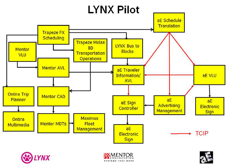
(Extended Text Description: Who is using TCIP? Examples and Real World Applications � Lynx Pilot This slide shows a snapshot of the FUTURE LYNX (Orlando) Agency ITS Architecture. Non-TCIP interfaces are shown by black lines connecting the boxes. TCIP interfaces are shown by red lines. Descriptions for non-generic boxes in the LYNX Architecture Trapeze Scheduling is a Transit Schedule Development Platform. This system provides data to Trapeze BD and to aE Schedule Translation which uses TCIP to interface with aE Traveler Information/AVL, aE Advertising Manager and aE VLU Trapeze BD Transportation Operations provides bid processing, dispatch control, and timekeeping and sends data to Mentor CAD Mentor AVL provides near-real time bus tracking data to Mentor CAD and to aE Traveler Information/AVL Mentor CADD provides computer assisted management of buses while they are en route as well as for initial dispatch. LYNX Bus to Blocks is a LYNX IT Application that manages the daily assignment of buses to blocks (work assignments) which also provides information to aE Traveler Information/AVL Ontira Trip Planner provides customers with address-to-address trip planning by combining a routing algorithm with dynamic mapping and provides data to Ontira Multimedia which provides customers with service information via a variety of communications media (phones, internet, kiosks, etc.).)
This slide shows a snapshot of the FUTURE LYNX (Orlando) Agency ITS Architecture. TCIP interfaces are shown by red lines.
Descriptions for non-generic boxes in the LYNX Architecture
- Trapeze Scheduling is a Transit Schedule Development Platform
- Trapeze BD provides bid processing, dispatch control, and timekeeping
- LYNX Bus to Blocks is a LYNX IT Application that manages the daily assignment of buses to blocks (work assignments)
- Ontira Trip Planner provides customers with address-to-address trip planning by combining a routing algorithm with dynamic mapping
- Ontira Multimedia provides customers with service information via a variety of communications media (phones, internet, kiosks, etc.)
- Maximus Fleet Management manages and schedules fleet maintenance, parts inventory, etc.
- Mentor AVL provides near-real time bus tracking
- Mentor CADD provides computer assisted management of buses while they are en route as well as for initial dispatch
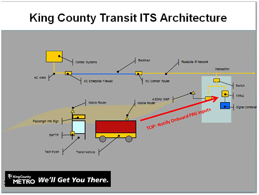
(Extended Text Description: Who is using TCIP? Examples and Real World Applications (cont.) � Author’s relevant notes, for illustration purposes only: King County Transit ITS Architecture This graphic shows the King County Metro architecture for Transit Signal Priority. TCIP will be used to communicate information that supports signal priority requests from buses to the traffic signal control system. The TCIP compliant interface is shown as a red line. The conversation between the Priority Request Generator (PRG) and the Priority Request Server (PRS) uses a different standard.)
This graphic shows the King County Metro architecture for Transit Signal Priority. TCIP will be used to communicate information that supports signal priority requests from buses to the traffic signal control system. The TCIP compliant interface is shown as a red line. The conversation between the Priority Request Generator (PRG) and the Priority Request Server (PRS) uses a different standard.
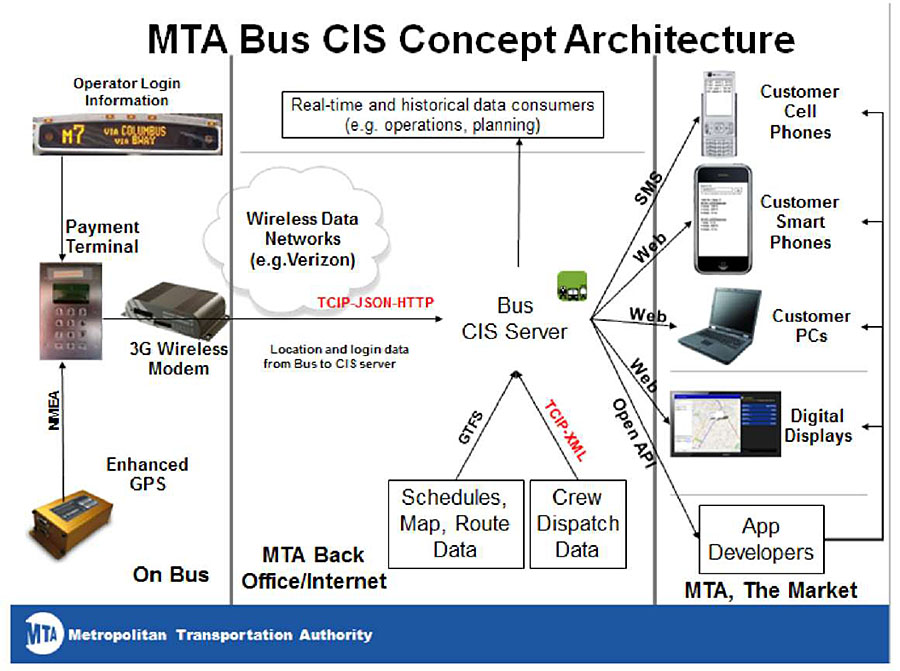
(Extended Text Description: Who is using TCIP? Examples and Real World Applications (cont.) � MTA Bus Time Technology � MTA Bus CIS Concept Architecture This graphic illustrates the New York MTA’s bus customer information system architecture. TCIP is used in conjunction with other standards to communicate real time bus arrival data every 30 seconds from 5,500 buses to the central server. On the left are shown components on a bus, including the Operator Login Information which is sent to the Payment Terminal. An enhanced GPS unit provides NEMA standard location data to the Payment Terminal which then sends location and login data from the bus to a 3G modem. The Verizon wireless data network sends the data which uses standards including TCIP, JSON and HTTP to the CIS server in the MTA back office. Here, GTFS standard is used to send Schedules, Map and Route Data to the Bus CIS Server. TCIP is used to send crew dispatch data to the Bus CIS Server. The Bus CIS Server uses SMS to send information to customer cell phones, and uses the web to send data to smart phones, customer PC’s, and digital displays.)
This graphic illustrates the New York MTA’s bus customer information system architecture. TCIP is used in conjunction with other standards to communicate real time bus arrival data every 30 seconds from 5,500 buses to the central server.
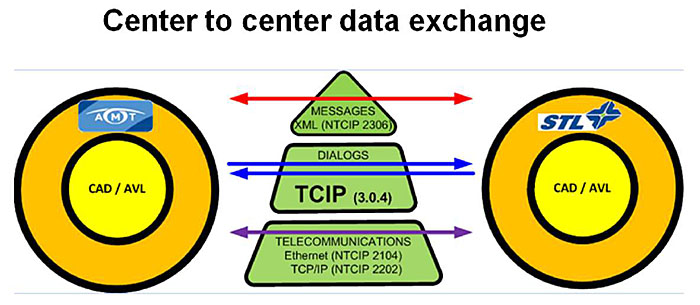
(Extended Text Description: Who is using TCIP? Examples and Real World Applications (cont.) AMT Montreal - This graphic illustrates how Montreal’s Agence Métropolitaine de Transport (AMT) uses TCIP dialogs to exchange data between two different CAD/AVL servers. A CAD/AVL Server for AMT is shown as a circle on the left. This exchanges data over a communications stack depicted as a triangle in the middle. On the right, a circle represents the CAD/AVL server for a sister agency, STL. The triangle segments in the middle illustrate the communication layers involved the exchange. Ethernet protocols are the bottom layer. TCIP is the next layer which is used to specify the dialogs. The messages in the dialogs are encoded in XML using the TCIP schema shown as the top layer.)
This graphic illustrates how Montreal’s Agence Metropolitaine de Transport (AMT) uses TCIP dialogs to exchange data between two different CAD/AVL servers.
The green triangle segments in the middle illustrate the communication layers involved the exchange. Ethernet protocols are the bottom layer. TCIP is the next layer which is used to specify the dialogs. The messages in the dialogs are encoded in XML using the TCIP schema.
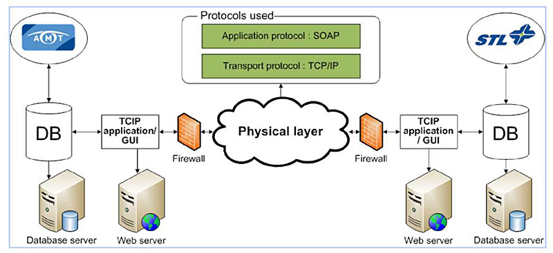
(Extended Text Description: This graphic illustrates the architecture used by AMT, showing where the TCIP dialogs fit in the communication layers. Icons representing two groups of servers on each end of the graphic are separated by and connected to firewalls and the physical layer of a network, represented by a cloud. The physical layer points up to two green boxes inside a larger box labeled "Protocols used". The topmost box is labeled "Applications Protocol - SOAP". The lower box is labeled Transport protocol - TCP/IP".)
This graphic illustrates the architecture used by AMT, showing where the TCIP dialogs fit in the communications layers, and other supporting layers and standards.
Example - Concept of Operations
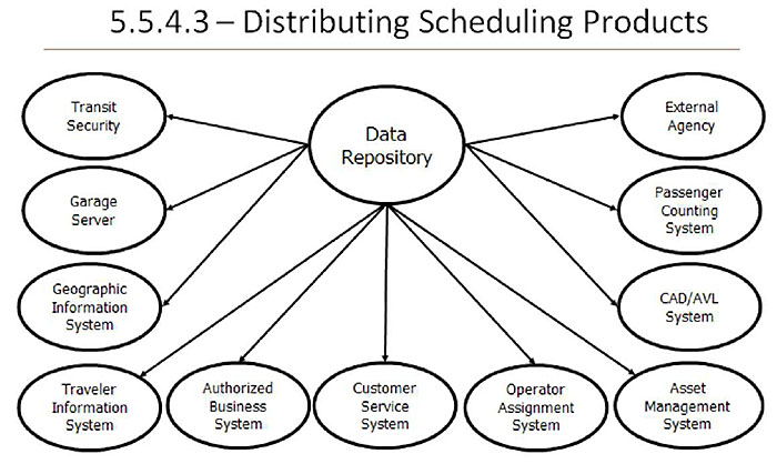
(Extended Text Description: TCIP Standard Volume I Section 5.5.4.3 Distributing Scheduling Products (continued) � This slide shows an oval in the center representing the data repository connected by arrows denoting data flows to eleven other ovals representing various business systems that need to receive scheduling products, including: Transit Security System, Garage Server, Geographic Information System, Traveler Information System, Customer Service System, Operator Assignment System, External Agency, Passenger Counting System, CAD/AVL System, Asset Management System, and other Authorized Business System.)
The graphic shows the concept of operations diagram for how scheduling products would be distributed to other business systems in the transit agency from a data repository
The graphic on this slide illustrates the Data Repository sending schedule information (that it received from the Scheduling System) to other associated units. If an agency does not have a Data Repository, the Scheduling System can directly send the schedule information to the associated units.
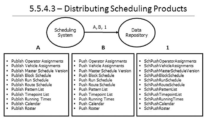
(Extended Text Description: This diagram is labeled "5.5.4.3 - Distributing Scheduling Products". Below that there are two circles connected by a line. The circle on the left is labeled "Scheduling System". The line is labeled "A, B, 1". The circle on the right is labeled "Data Repository". Beneath those circles are three boxes. The box labeled A contains the following text:
- Publish Operator Assignments
- Publish Vehicle Assignments
- Publish Master Schedule Version
- Publish Block Schedule
- Publish Run Schedule
- Publish Route Schedule
- Publish Pattern List
- Publish Timeport List
- Publish Running Times
- Publish Calendar
- Publish Roster
The box labeled B contains the following text:
- Push Operator Assignments
- Push Vehicle Assignments
- Push Master Schedule Version
- Push Block Schedule
- Publish Run Schedule
- Push Route Schedule
- Push Pattern List
- Push Timeport List
- Push Running Times
- Push Calendar
- Push Roster
The box labeled I contains the following text:
- SchPushOperatorAssignments
- SchPushVehicleAssignments
- SchPushMasterScheduleVersion
- SchPushBlockSchedule
- PublushRunSchedule
- SchPushRouteSchedule
- SchPushPatternList
- SchPushTimeportList
- SchPushRunningTimes
- SchPushCalendar
- SchPushRoster
The graphic replicates a portion of the concept of operations diagram showing how scheduling system products are distributed to a data repository. New schedules are generated by scheduling system software. They are then distributed to a data repository where they can be stored and distributed to other business systems.
For this example, we will focus on the sub-process of "Distributing scheduling products" (i.e., 5.5.4.3 in the TCIP Standard Volume 1). In this case, the Scheduling System is sending the schedule data to the Data Repository.
"A" = Schedule product distributed via a "publish-subscribe" dialog "B" = Schedule product distributed via a "push" to all receivers dialog "1" = Schedule product distributed via a file transfer
3. Case Study
The following case study illustrates the development of an agency architecture as new ITS systems are added over a five year period.
Current Agency ITS Architecture and Operations shown in Figure 1
- The legacy agency architecture includes:
- A commercial scheduling application that is used to develop a new schedule on a quarterly basis.
- A commercial pick system, which has been customized for the agency to account for business rules related to the agency’s labor agreements.
- An agency-developed database that stores the schedules and pick results.
- An agency developed Bus Manager application. This application is the key to day-to-day operations. It maintains the readiness status and maintenance schedules for all buses, and is used by supervisors to make operator assignment changes based on daily occurrences such as sick time, vacation time, training, etc.
- A Fare System consisting of a Farebox/MDT onboard the buses and a Fare Central Server that keeps track of the revenues received. The onboard fare computers communicate with the Fare Central Server via a proprietary, secure short range infrared communications link in the area where the fare boxes are unloaded.
Recent Developments
A public referendum was voted on, that resulted in 0.5% of the local sales tax being dedicated to use for transit improvements. The agency was tasked by the Metropolitan Planning Organization (MPO) to develop a plan to upgrade the Agency’s Systems to improve the quantity and quality of information provided to the public, and to improve operational efficiency. After some internal planning and debate, the agency developed a set of 3 and 5 year goals for upgrades to its business systems and these were approved by the MPO.
The agency’s goals for the first 3 years are to implement:
- A Web-based Itinerary Planner that allows the public to obtain a trip based on the transit schedule that will be in effect at the time of the desired trip.
- Automatic Vehicle Annunciation (AVA) that provides automated stop announcements on all buses, as well as automatic updates to the bus headsigns.
- Automatic Vehicle Monitoring (AVM) that monitors the health status of each bus and provides this information to the Bus Manager application when in the garage area.
Within 5 years, the agency’s goals are to implement:
- A Computer Aided Dispatch/Automatic Vehicle Location System (CAD/AVL) that will improve the ability of managers and supervisors at the garages and the agency headquarters to visualize the service being provided in near-real-time, and to allow a reduction in the number of roving street supervisors.
- A real-time bus arrival traveler information system to notify the public where the next bus is for a given route, and to provide notifications of ongoing and planned service disruptions and changes.
- Service status signs at high volume bus stops and transfer locations displaying real time bus arrival and service disruption information
- A new vehicle logic unit with Single Sign-On (SSO) so that the drivers are not required to separately sign on to AVA, AVM, and the fare system
The three following figures show: 1) the baseline architecture, 2) the year three architecture, and 3) year five architecture.
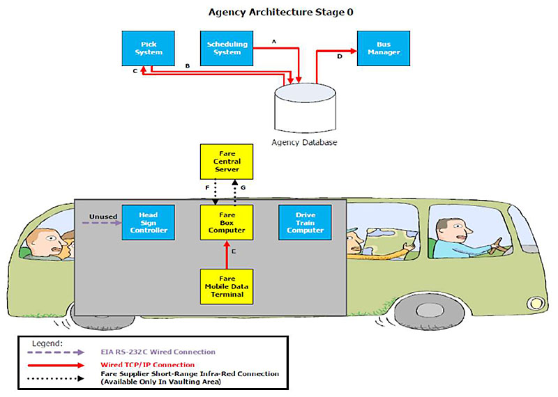
(Extended Text Description: Diagramming an agency architecture This figure illustrates an agency architecture diagram showing a base year configuration of systems on the bus and in the management center. Boxes represent various systems and lines with arrows show the data flows among the systems. A pick system*, a scheduling system and a bus manager system all interface with the agency database using TCP/IP internet type connections. On the bus, a head sign controller and the drive train computers operate independently. A Fare Mobile Data Terminal on the bus has a wired connection to the farebox computer. The farebox computer can exchange data with a central fare server at the garage using an infra-red connection. The agency has plans to add additional functionality in year 3 of their ITS capital program and how the architecture changes will be seen in the next slide. *A "pick" system is one that is used for drivers to choose work assignments. Some agencies refer to these systems as "sign-up" systems or use other names.)
Figure 1 Current Agency Architecture and Legacy Systems
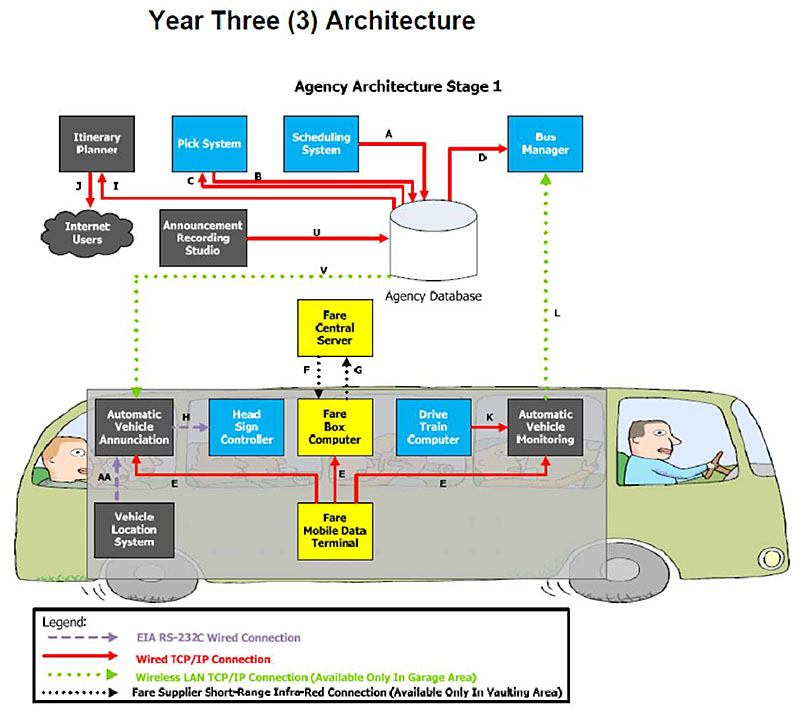
(Extended Text Description: Diagramming an agency architecture (continued) Year 3 Architecture - This slide is to be compared with the previous one to show the second stage of implementation for the agency’s ITS architecture. Boxes represent various systems and lines with arrows show the data flows among the systems. In year 3, the agency intends to add: an itinerary planner that directly feeds customers via the internet, an announcement recording studio system, an automatic vehicle stop annunciation system, a vehicle location system, and an automatic vehicle health monitoring system These systems will require more integration with other systems and the architecture has added lines representing additional data communication flows. Data flows between the bus and the management center now will use wireless local area networks.)
Figure 2 Year 3 Architecture showing:
- A Web-based Itinerary Planner that allows the public to obtain a trip based on the transit schedule that will be in effect at the time of the desired trip.
- Automatic Vehicle Annunciation (AVA) that provides automated stop announcements on all buses, as well as automatic updates to the bus headsigns.
- Automatic Vehicle Monitoring (AVM) that monitors the health status of each bus and provides this information to the Bus Manager application when in the garage area.

(Extended Text Description: Diagramming an agency architecture (continued) - Year 5 Architecture The year 5 architecture adds long range wireless data communications between the vehicle and the management center. Additional boxes representing systems and lines representing data flows are added. On board the bus, the vehicle location system, which had been used in year 3 only to drive an automatic stop annunciator system, now has its location data sent via the stop annunciator to the vehicle logic unit, which allows the bus location to be transmitted back to a computer aided dispatch/automatic vehicle location (CAD/AVL) system. The CAD/AVL system now sends data to a Traveler Information System which in turn feeds data to Electronic Bus Stop Sign Displays.)
Figure 3 showing the year 5 architecture with the following new systems:
- A Computer Aided Dispatch/Automatic Vehicle Location System (CAD/AVL) that will improve the ability of managers and supervisors at the garages and the agency headquarters to visualize the service being provided in near-real-time, and to allow a reduction in the number of roving street supervisors.
- A real-time bus arrival traveler information system to notify the public where the next bus is for a given route, and to provide notifications of ongoing and planned service disruptions and changes.
- Service status signs at high volume bus stops and transfer locations displaying real time bus arrival and service disruption information
- A new vehicle logic unit with Single Sign-On (SSO) so that the drivers are not required to separately sign on to AVA, AVM, and the fare system
4. Glossary
| Term | Definition |
|---|---|
| Agency ITS Architecture | The repository for capturing and documenting the agency’s legacy and planned business systems, legacy interfaces, as well as the TCIP interfaces. The agency ITS architecture may specify a series of development phases for the agency’s ITS systems |
| Agency Specification | A document that has been prepared by an agency to define requirements for a subject item or process when procured by the agency. |
| APTA | American Public Transportation Association. Serves and leads its diverse membership through advocacy, innovation, and information sharing to strengthen and expand public transportation |
| Compliance | A condition that exists when an item meets all of the requirements of an agency specification. |
| Concept of Operations | A document that describes the purpose for a system project, including a description of the current and proposed system, as well as key user needs that the new system is required to address. |
| Conformance | A condition that exists when an item meets all of the mandatory requirements as defined by a standard. It can be measured on the standard as a whole, which means that it meets all mandatory (and applicable conditional) requirements of the standard or on a feature level (i.e., it conforms to feature X as defined in section X.X.X), which means that it meets all mandatory (and applicable conditional) requirements of the feature. |
| Data element | An atomic piece of information related to a person, place, thing, or concept. For example, CPT-PersonFirstName and CPT-Footnote are data elements |
| Data frame | A grouping of data elements primarily for the purpose of referring to a group with a single name, and thereby efficiently reusing groups of data elements that commonly appear together (as an ASN.1 Sequence, Sequence Of , or Choice) in a TCIP message. This data concept type may also be used to specify groups of data elements for other purposes as well. A data frame may contain other data frames as well as data elements. |
| Data repository | A business system in a transportation organization, whose primary function is to accept and store agency data, which may include the output of other business systems, and to make the data available to authorized business systems on demand. Some repositories may combine data from different business systems and provide the results on request, or may process the data and provide the processed result to authorized business systems. |
| Dialog | An ordered sequence of message exchanges between two or more entities. The rules of the exchange are defined by a dialog pattern. Messages specific to the type of exchange are specified by the dialog. |
| Dialog Pattern | A description of a message exchange between two or more entities, including the rules associated with the exchange. Generally, the same pattern can be used to convey more than one type of information. For example, a Publication could convey schedules or alarm information. |
| File Transfer | An information transfer effected between two computers by having one computer write information to a file, moving the file to the other computer and, having the second computer read the file. In the case of a TCIP file transfer, the file is an XML document consisting of a single TCIP message. |
| Interface | The point of interaction between a business system, subsystem, or component, and any other entity. |
| LRMS | Location Referencing Message Specification. SAE Standard J2266. Standardizes location referencing for ITS applications that require the communication of spatial data references between databases or computer applications. |
| Message | A grouping of data elements and/or data frames intended to be transmitted as a complete package of information in one direction. |
| Model architecture | A generic representation to illustrate the range of intelligent transportation systems and interfaces within a transit agency as well as the interfaces between the agency and other agencies and/or private entities |
| National ITS Architecture | Provides a common framework for planning, defining, and integrating intelligent transportation systems |
| Profile Implementation Conformance Statement (PICS) | A document used to specify the TCIP interface(s) associated with an implementation. The PICS lists the TCIP dialogs, TCIP message file transfers, and options supported by the implementation along with other detailed information about the interface. |
| Profile Requirements List (PRL) | A document used to specify an agency’s requirements for the TCIP interface(s) associated with a new or upgraded system. The PRL lists the TCIP dialogs, TCIP message file transfers, and options required for the interface along with other detailed interface information. |
| Regional ITS architecture | A common framework for planning, defining, and integrating intelligent transportation systems within a metropolitan region |
| Scheduling system | A business system that creates transit schedules and organizes planned trips within that schedule into operator and vehicle assignments. |
| Timepoint | A point along a public transit vehicle’s route where the vehicle’s scheduled time to traverse that point is identified in the schedule. Timepoints may be defined and not used in the schedule, or may be used in more than one route. |
| Transit business system | A fixed computer application within the Model Architecture that performs a particular business function or group of related functions. |
| TCIP Implementation & Requirements Capabilities Editor (TIRCE) | A software application to document agency requirements and specifications for TCIP interfaces, vendor product capabilities, and allow the capabilities to be compared with the requirements |
| Transit signal priority | A TCIP business area related to obtaining preferential treatment for public transit vehicles at signalized intersections. |
5. References
"NTI Instructor Materials: Integrating Transit Applications: Defining Data Interfaces Using TCIP," Power Point Presentation, NTI, February, 2012
J. Fayos, draft "NTI Instructor Materials: Integrating Transit Applications: Defining Data Interfaces Using TCIP," NTI, August, 2013
Figure 9.2 "TCIP Provides the Building Blocks for Agency ITS architectures and RFPs," APTA TCIP-S-001 4.0.0 Volume I, p 328,
Concept of operations - Wikipedia, the free encyclopedia, accessed July 12, 2014 https://www.google.com/search?q=definition+concept+of+operations&rlz=1C1LDJZ_enUS499US518&oq=definition+concept+of+&aqs=chrome.1.69i57j0l5.7685j0j8&sourceid=chrome&es_sm=122&ie=UTF-8
ITS PCB T3 Webinars on ITS Transit Standards t3_archives.aspx
"Integrating Transit Applications: Defining Data Interface Requirements Using TCIP - Participant Workbook" Accessed September 23, 2014
6. Study Questions
-
What is the purpose of the TCIP standard?
- Ensure all transit agencies conform to same requirements
- Federal requirement on uniformity for all procurements
- Exchange information for transit ITS systems & components
- TCIP is the only standard allowed for transit ITS systems
-
What is the role of balloting in developing a standard?
- To elect members to standards bodies
- Ensure that a consensus has been achieved on the standard
- Transit agencies’ majority vote is needed to create a standard
- Ensures that Federal reps agree to require the standard
-
Which factor is most likely to lead to changes in communication systems?
- New technology becomes available
- Transit systems expand into new modes
- New management requirements increase information demand
- New transit vehicles require new radios
-
Which is a key risk in transit ITS procurements?
- Separately procured systems won’t communicate
- Transit agencies may be overcharged for ITS systems
- Legacy systems do not have backups
- Standards are not available to integrate systems
-
Which is a benefit of using TCIP in transit ITS procurements?
- Standardize internal components of a vendor’s ITS system
- Lower initial procurement costs
- Allow multiple vendors to compete
- Expand the bandwidth for communications between systems
-
Which answer best describes the use of an agency architecture to aid on capital and project planning?
- Shows the building needed to house new systems
- Specifies the costs of systems for budgeting
- Must specify how vehicles communicate with control center
- Shows which systems need to interface with other systems
-
What are the key elements displayed in an architecture diagram?
- All transit vehicles and fixed facilities in a system
- All business processes in agency concept of operations
- Only those components that are TCIP compliant
- Selected business systems and data flows
-
How can TCIP be used to transfer data?
- Transfer data in files and real-time dialogs
- Only transfer data in real-time dialogs
- Transfer data in publish-subscribe mode
- Transfer data only over the internet
-
Which statement most accurately characterizes a TCIP dialog?
- A TCIP dialog is a sequence of data elements
- A TCIP dialog is a digital voice communication pattern
- A TCIP dialog is a structured exchange of messages
- A TCIP dialog is a message with two parts
-
Why does TCIP include a suite of tools?
- To fix bugs in the standard
- To develop an agency architecture
- To allow developers to revise and re-ballot the standard
- To develop procurement documents and test compliance
-
In what types of applications could my agency use TCIP?
- Control center to control center
- Database to web servers
- Communicate real time bus arrival information
- Communicate between vehicles and base
- All of the above