ITS Transit Standards Professional Capacity Building Program
Module 4: Transit Communications Interface Profiles (TCIP), Part 2 of 2: Structure and Elements of TCIP - Accessing TCIP via TIRCE and TCIP Tools
HTML of the PowerPoint Presentation
(Note: This document has been converted from a PowerPoint presentation to 508-compliant HTML. The formatting has been adjusted for 508 compliance, but all the original text content is included, plus additional text descriptions for the images, photos and/or diagrams have been provided below.)
Slide 1:

(Extended Text Description: Welcome - Graphic image of introductory slide. A large dark blue rectangle with a wide, light grid pattern at the top half and bands of dark and lighter blue bands below. There is a white square ITS logo box with words "Standards ITS Training" in green and blue on the middle left side. The word "Welcome" in white is to the right of the logo. Under the logo box is the logo for the U.S. Department of Transportation, Office of the Assistant Secretary for Research and Technology.)
Slide 2:
(Extended Text Description: This slide, entitled "Mac Lister" has a photo of Mac Lister, Program Manager Knowledge and Technology Transfer, ITS Joint Program Office, on the left hand side, with his email address, Mac.Lister@dot.gov. A screen capture snapshot of the home webpage is found on the right hand side - for illustration only - from August 2014. Below this image is a link to the current website: www.its.dot.gov/pcb - this screen capture snapshot shows an example from the Office of the Assistant Secretary for Research and Development - Intelligent Transportation Systems Joint Program Office - ITS Professional Capacity Building Program/Advanced ITS Education. Below the main site banner, it shows the main navigation menu with the following items: About, ITS Training, Knowledge Exchange, Technology Transfer, ITS in Academics, and Media Library. Below the main navigation menu, the page shows various content of the website, including a graphic image of professionals seated in a room during a training program. A text overlay has the text Welcome to ITS Professional Capacity Building. Additional content on the page includes a box entitled What’s New and a section labeled Free Training. Again, this image serves for illustration only. The current website link is: https://www.its.dot.gov/pcb.)
Slide 3:
(Extended Text Description: This slide, entitled "Jeffrey Spencer" has a photo of Jeffrey Spencer, ITS Team Leader, Federal Transit Administration, Office of Research, Demonstration and Innovation, on the left hand side, with his email address, Jeffrey.Spencer@dot.gov. A screen capture snapshot of the home webpage is found on the right hand side - for illustration only - which is the same screen snapshot from Slide 2. Below this image and to the right is the Federal Transit Administration (FTA) logo.)
Slide 4:
ITS Transit Standards Professional Capacity Building Program
Module 4:
Transit Communications Interface Profiles (TCIP), Part 2 of 2: Structure and Elements of TCIP—Accessing TCIP via TIRCE and TCIP Tools
Slide 5:
Acknowledgments
- Ayers Electronic Systems, LLC
- Critical Link, LLC
- National Transit Institute
Slide 6:

Slide 7:
Instructor

Jerome M. Lutin, Ph.D., P.E., AICP
Senior Director (Retired)
New Jersey Transit
South Brunswick, NJ, USA
Slide 8:
Target Audience
- Transit procurements staff;
- Transit IT staff;
- Metropolitan Planning Organizations (MPO) staff;
- Department of Transportation (DOT)/ITS staff;
- Transit ITS contractors and consultants;
- Transit technology vendors;
- Transit Traveler Information System managers; and
- Traffic Management Center (TMC) / Traffic Operation Center (TOC) managers.
Slide 9:
Recommended Prerequisite(s)
| Decision-Maker | Project Manager | Project Engineer | |
|---|---|---|---|
| Module 1: Introduction to ITS Transit Standards | N/A | ✓ | ✓ |
| Module 2: Transit Management, Part 1 of 2 | N/A | ✓ | ✓ |
| Module 3: Transit Communications Interface Profiles (TCIP), Part 1 of 2 | N/A | ✓ | ✓ |
| Module 5: Transit Management, Part 2 of 2 | N/A | ✓ | ✓ |
Slide 10:
Curriculum Path (Project Manager)
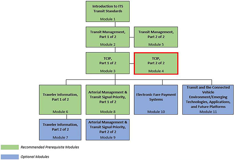
(Extended Text Description: Curriculum Path for Project Manager. A graphical illustration indicating the sequence of training modules and where this module fits in. Each module is represented by a box with the name of the module in it and a flow chart showing the logical flow of the modules with the current module boxed in red. The first three horizontally sequenced boxes are green. The first box is "Introduction to ITS Transit Standards, Module 1." Below that, connected by a line, is a box with the text "Transit Management, Part 1 of 2." To the right of this box, is "Transit Management, Part 2 of 2". Below "Transit Management, Part 1 of 2", connected by a line, is a box with the text, "TCIP, Part 1 of 2". To the right of this box, is "TCIP, Part 2 of 2", which is outlined in red. From here, the lines branch out into four text boxes that are horizontally sequenced. The first two: "Traveler Information, Part 1 of 2" and "Arterial Management & Transit Signal Priority, Part 1 of 2" are green; the last two, in blue, are "Electronic Fare Payment Systems" and "Transit and the Connected Vehicle Environment/Emerging Technologies, Applications, and Future Platforms". Below "Traveler Information, Part 1 of 2," is the text box "Traveler Information, Part 2 of 2" coded in blue. Below "Arterial Management & Transit Signal Priority, Part 1 of 2" is the text box, "Arterial Management & Transit Signal Priority, Part 2 of 2", coded in blue.)
Slide 11:
Curriculum Path (Project Engineer)
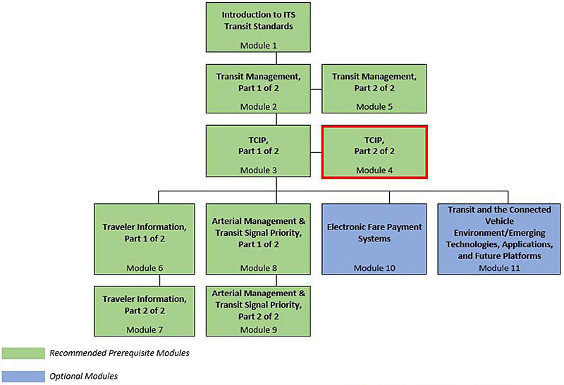
(Extended Text Description: Curriculum Path for Project Engineer. A graphical illustration indicating the sequence of training modules and where this module fits in. Each module is represented by a box with the name of the module in it and a flow chart showing the logical flow of the modules with the current module boxed in red. The first three horizontally sequenced boxes are green. The first box is "Introduction to ITS Transit Standards, Module 1." Below that, connected by a line, is a box with the text "Transit Management, Part 1 of 2." To the right of this box, is "Transit Management, Part 2 of 2". Below that "Transit Management, Part 1 of 2", connected by a line, is a box with the text, "TCIP, Part 1 of 2". To the right of this box, is "TCIP, Part 2 of 2", which is outlined in red. From here, the lines branch out into four text boxes that are horizontally sequenced. The first two: "Traveler Information, Part 1 of 2" and "Arterial Management & Transit Signal Priority, Part 1 of 2" are green; the last two, in blue, are "Electronic Fare Payment Systems" and "Transit and the Connected Vehicle Environment/Emerging Technologies, Applications, and Future Platforms." Below "Traveler Information, Part 1 of 2," is the text box "Traveler Information, Part 2 of 2 coded in green. Below "Arterial Management & Transit Signal Priority, Part 1 of 2", is the text box "Arterial Management & Transit Signal Priority, Part 2 of 2, coded in green.)
Slide 12:
Learning Objectives
- Illustrate the "communications stack" and show how it relates to TCIP.
- Describe the TCIP Implementation, Requirements and Capabilities Editor (TIRCE) and how it is used as the key to TCIP.
- Identify and provide examples of data elements, data frames, messages, and dialogs.
- Describe how data are organized in TCIP data exchanges
- Define a Profile Requirements List (PRL) and explain how it is used to specify TCIP requirements in a transit ITS project.
- Articulate and describe the uses of each tool in the TCIP suite of tools.
- Summarize the range of TCIP applications, implementation tools, and additional training.
Slide 13:
Learning Objective #1: Illustrate the "Communications Stack" and Show How It Relates to TCIP
- Communications layers
- TCIP model for data exchange
- File transfer and real time
Slide 14:
Learning Objective #1
Open Systems Interconnection (OSI) Model
| Open Systems Interconnection (OSI) Model |
|---|
| 7. Application Layer - Message Format - TCIP is used in this layer |
| 6. Presentation Layer - Encryption/decryption - XML is used in this layer |
| 5. Session Layer - Manages connection between computers |
| 4. Transport Layer - Creates segments or "packets" of data |
| 3. Network Layer -Addressing and routing |
| 2. Data Link Layer - Access to physical layer, error detection |
| 1. Physical Layer - Electrical properties of connection |
Slide 15:
Learning Objective #1
TCIP Model for Data Exchange
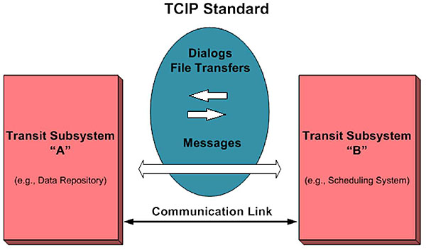
(Extended Text Description: Author’s relevant notes: Integrating systems using TCIP. This figure illustrates the TCIP model for data exchange. Transit subsystems are represented by blocks on the right and on the left. Between the blocks arrows represent the flow of data between them over an arrow representing the communications link. TCIP dialogs and file transfers are represented by an oval sitting above the communications link showing messages encoded using TCIP exchange profiles.)
Slide 16:
Learning Objective #1
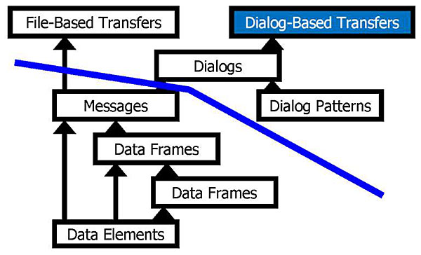
TCIP Building Blocks
This graphic illustrates the distinction between what data are transferred, which is shown below the blue line; and how the data are transferred, which is shown above the blue line.
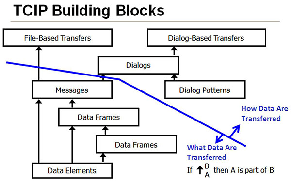
(Extended Text Description: Author’s relevant notes: TCIP Building Blocks. This figure shows a series of boxes arranged in a hierarchy below a line. The hierarchy starts with a box at the bottom representing data elements. This box is linked to boxes above it with arrows representing the buildup of higher levels of structure for data. These levels represent data frames and messages. These boxes represent what data is being transferred. The message box just below the line represents "messages" the highest level of the "what" that is being transferred. Above the line are boxes that represent how data is transferred. Messages are linked by arrows crossing the line to a box representing file based transfers and to a box representing dialogs. A box representing dialog patterns feeds into the dialog box. The dialog box in turn feeds a box representing dialog-based transfers. This diagram is used in subsequent slides with the relevant box highlighted respectively for the item being discussed in the slide.)
Slide 17:
Learning Objective #1
How Data Are Transferred - File-Based Exchange
Transfer Data Without the Use of Dialogs in a Non-Real-Time Manner
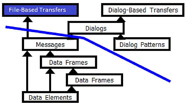
(Extended Text Description: This slide uses the diagram shown in Slide #16 with the box labeled "File-Based Transfers" highlighted.)
- Computer application saves data in a file
- File is transferred to another system
-
File is loaded and read by another computer application
- Sometimes involves human interaction
-
This interaction requires an agreed-upon description for the files
- TCIP messages provide this description
Slide 18:
Learning Objective #1
Dialogs
Specify the Operational Purpose, Dialog Pattern, Messages, and Other Special Conditions/Constraints
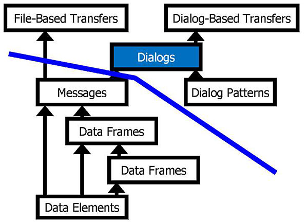
(Extended Text Description: This slide uses the diagram shown in Slide #16 with the box labeled "Dialogs" highlighted.)
| Publication Dialog Definition - Refer to Section 7.1 | ||
| Dialog Name: Business Area: Publish Fleet Locations CC | ||
| Dialog Purpose: Allows a subscriber to obtain PTV locations by subscribing through a single business system (e.g. CAD/AVL) rather than subscribing to each PTV individually. | ||
| Publication Type: Event | ||
| Row Updates Supported: None | ||
|
Publication Request and Response Messages: Request: Response: Error response: |
Name [CcFleetLocationSub] [CcFleetLocation] [CptSubErrorNotice] |
Identifier Cc 2063 Cc 2064 Cpt2000 |
Slide 19:
Learning Objective #1
Dialog-Based Transfer
Real-Time Transfer (Machine-to-Machine) Using Dialogs
(Extended Text Description: This slide uses the diagram shown in Slide #16 with the box labeled "Dialog-Based Transfers" highlighted.)
-
Does not define:
- How data are stored, translated, and manipulated
- How data are formatted and presented to human users
- How systems/components trigger or initiate dialogs
- Details of the interactions with human users
Slide 20:
Learning Objective #1
Dialog Patterns
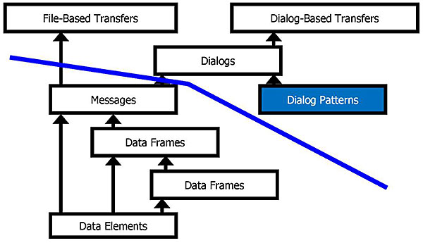
(Extended Text Description: This slide uses the diagram shown in Slide #16 with the box labeled "Dialog Patterns" highlighted.)
- Defines the sequence of actions for a dialog
- Can be reused for multiple purposes
Slide 21:

Slide 22:
Learning Objective #1
Which of the following is defined in a TCIP dialog?
Answer Choices
- How data are stored and translated
- How data are formatted
- How systems present data to human users
- How messages are sequenced
Slide 23:
Learning Objective #1
Review of Answers
 a) How data are stored and translated
Incorrect. Dialogs do not determine how data are stored and translated.
b) How data are formatted
Incorrect. Dialogs do not determine how data are formatted.
c) How systems present data to human users
Incorrect. Dialogs do not determine how data are presented to human users.
 d) How messages are sequenced
Correct! Dialogs specify the sequential order of messages.
Slide 24:
Summary of Learning Objective #1
Illustrate the "Communications Stack" and Show How It Relates to TCIP
- There are seven layers in the OSI model "communications stack"
- TCIP model for data exchange includes the "what," which are data elements, data frames, and messages, and the "how," which are file transfers, dialogs, and dialog patterns
- TCIP can exchange data in both file transfer and real time
Slide 25:
Learning Objective #2: Describe the TCIP Implementation, Requirements and Capabilities Editor (TIRCE) and How It Is Used as the Key to TCIP
- Interface specification
- Agency perspective - defining business applications by creating a Profile Requirements List (PRL)
- Vendor perspective - testing product compliance using a Profile Implementation Conformance Statement (PICS)
Slide 26:
Learning Objective #2
Interface Specification
Detailed Interface Specifications Are Critical for Success
- Ability to understand (and specify) exactly what information is to be exchanged across the interface (both the "how" and the "what")
- Minimizes opportunities for agency/vendor technical disconnects
- Provides verification test criteria
- Maintenance and future upgrades
Slide 27:
Learning Objective #2
Interface Specification (cont.)
TIRCE - for Interface Specification
- Guides user through a step-by-step process of converting an agency’s functional requirements into a TCIP-compliant specification
-
A top-down systems engineering approach to defining the data exchange interfaces between transit components
- Information that will be exchanged
- Manner in which information is exchanged
Slide 28:
Learning Objective #2
Interface Specification (cont.)
The Five Tabs of TIRCE
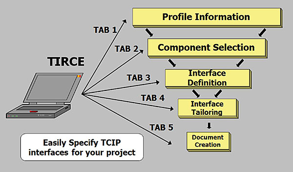
(Extended Text Description: This slide shows a laptop computer on the left with arrows pointing to five boxes each labeled with one of the five tabs of TIRCE. Starting at the top with Tab 1, Profile Information, arrows lead to the next box below, Tab 2 Component Selection, and then to succeeding boxes for each tab. There are five tabs to create a Profile Requirements List (PRL) document or Profile Implementation Conformance Statement (PICS) document. TIRCE will prompt the user for information at each of the five tabs. Tab 1 Profile Information includes overall information such as agency name and project name. Tab 2 Component Selection allows the user to select specific components between which data will be exchanged and for which an interface must be specified. Tab 3 Interface Definition allows the user to select the TCIP dialogs and file transfers that each interface they will use. These services describe the message traffic that will occur between Project Component and its External Component. Tab 4 Interface Tailoring walks the user through a series of questions designed to help them specify the details of the information that will be exchanged across the interfaces. This step helps the user populate individual message fields within the communications selected for their project. Tab 5 Document Creation. At any point in the process, the user can select the Document Creation tab to see a version of the document created up to that point. Once all interfaces have been identified and tailored, the user is given the opportunity to check their newly created document for errors and export it in MS Word format.)
Slide 29:
Learning Objective #2
PRL and PICS
Profile Requirements List (PRL)
Profile Implementation Conformance Statement (PICS)
-
PRL and PICS are very similar in structure
- PRL defines the interface from the agency’s perspective
- PICS defines the interface from the vendor’s perspective
- Both define the TCIP dialogs and messages for each interface in the system
Slide 30:
Learning Objective #2
TIRCE - Agency Perspective
Profile Requirements List (PRL)
-
Generates detailed interface requirements
- Top-down systems engineering approach
- Interface requirements embodied in the PRL
- Allows an agency to define a project incrementally over time
- Quickly compare vendor responses to RFP requirements as stated in the PICS
Slide 31:
Learning Objective #2
TIRCE - Vendor Perspective
Profile Implementation Conformance Statement (PICS)
- Provides TCIP-compliance "spec-sheet" for vendors’ products (PICS)
- Provides a structured, precise response to interface requirements in a PRL
- Quickly evaluate RFPs against existing product capabilities (Diff)
-
Software development support
- Tailored XML Schema
Slide 32:
Learning Objective #2
TIRCE - Agency and Vendor Perspective
- TIRCE includes a Diff function to compare the PRL and PICS
Slide 33:

Slide 34:
Learning Objective #2
Which statement best characterizes a Profile Requirements List (PRL)?
Answer Choices
- A PRL includes a Diff function
- A PRL is developed by the vendor
- A PRL specifies the size of the files in the data exchange
- A PRL is developed by the agency
Slide 35:
Learning Objective #2
Review of Answers
a) A PRL includes a Diff function
Incorrect. The Diff function is used to compare the PRL and PICS.
b) A PRL is developed by the vendor
Incorrect. The PRL is developed by the procuring agency.
c) A PRL specifies the size of the files in the data exchange
Incorrect. The PRL does not specify the size of the files.
d) A PRL is developed by the agency
Correct! The PRL is developed by the procuring agency.
Slide 36:
Summary of Learning Objective #2: Describe the TCIP Implementation, Requirements and Capabilities Editor (TIRCE), and How It Is Used as the Key to TCIP
- Interface specification: TIRCE provides detailed specifications and XML schema for interfaces between machines that are exchanging data
- Agency perspective: Create a PRL that defines the components to be connected, the interfaces needed, and the dialogs to be implemented to facilitate the data exchange
- Vendor perspective: Create a PICS document that allows a vendor’s product to be compared with an agency’s requirements
Slide 37:
Learning Objective #3: Identify and Provide Examples of Data Elements, Data Frames, Messages, and Dialogs
- Data elements
- Data frames
- Messages
- Dialogs
- Dialog patterns
Slide 38:
Learning Objective #3
Data Element
-
An atomic piece of information related to a person, place, thing, or concept
-
Examples:
- SCH-TimepointID - a timepoint alphanumeric identifier
- SCH-TimepointName - a timepoint name
- LRMS.Latitude - latitude in microdegrees
-
Examples:
Slide 39:
Learning Objective #3
Data Elements (cont.)
-
TCIP Data Types are based on Abstract Syntax Notation (ASN.1)
- BOOLEAN
- ENUMERATED
- INTEGER
- UTF8String
- Numeric String
- OCTET String
-
TCIP has extended ASN.1 - created subtypes
- Integer subtypes
- Date and Time subtypes
- String, Name, and Identifier subtypes
Slide 40:
Learning Objective #3
Data Frames
- Groupings of data elements and other data frames to describe more complex concepts
- The groupings help organize information to describe or identify objects or concepts in the real world
-
Examples:
-
SCHTimepointIden identifies a timepoint
- Contains the data element with its unique alphanumeric identifier (SCH-TimepointID) and can also contain optional data elements including agency number and name
-
SCHTimepointInfo describes a timepoint
- Contains its identifier and location
-
SCHTimepointIden identifies a timepoint
Slide 41:
Learning Objective #3
TCIP Messages
- Aggregations of data elements and data frames into a larger, more complex structure
- A complete, understandable, one-way communication that consists of data elements and data frames conveying metadata and information
- For example, CptStoppointList is a message transmitting a list of all stop points
Slide 42:
Learning Objective #3
TCIP Message Example "SchTimepointList"
C.319 Message ScliTiinepomtList {Sell 2007}
Use:
Provide a specified version of timepoint information
Remarks:
A timepoint may be used in more than one pattern.
An agency may decide to include alltimepoints for th e agency with in a timepoint version, or to limit a version to the timepoints included on a route or group of routes, however all timepoints referenced in a pattern list (SchPattemList message) must be included in the version of the timepoints referenced by that pattern list. The update-thru field that the information provided reflects all updates thru the indicated datetime. This message can be used to convey changes to a timepoint list version since a specified time. In such a case, the update-since field indicates the date/time from which updates are provided. The deleted-timepoints field indicate timepoints deleted from the list since update-begin.
ASN1:
SchTimepointList ::= SEQUENCE {
subscriptionInfo CPTSubscriptionHeader,
languages CPTLanguageList OPTIONAL,
update-since CPT-DateTime OPTIONAL,
timepointVersion SCH-Time tableVersionID OPTIONAL,
effective CPT-Date Time,
expires CPT-Date Time OPTIONAL,
timepoints SEQUENCE (SIZE(1..10000)) OF SCHTimepointInfo OPTIONAL,
deleted-timepoints SEQUENCE (SIZE (1..25000)) OF SCHTimepointIden OPTIONAL
}|
The following dialogs use this message:
Publish Timepoint List
Slide 43:
Learning Objective #3
TCIP Dialogs
-
Dialogs specify:
- The operational purpose of the exchange of information
- Dialog pattern
- Messages included in the dialog
- Special conditions/constraints
- Relationships with other dialogs
Slide 44:
Learning Objective #3
TCIP Dialog Example: "Publish Timepoint List"
D.147 Dialog Publish Timepoint List
Use:
Allows a subscriber to obtain timepoint information by effective datetime or version number. The subscriber can determine the required timepoint effective date/version number using the Publish Master Schedule Version dialog.
Remarks:
The dialog may be used to re quest updates to a timepoint list since a specified date/time if the subscriber has previously obtained the complete timepoint list with the specified effective date or version number.
Dialog Contents
| Message | Role | File Transfer |
|---|---|---|
| SenTimepointListSub | Request | No |
| SenTimepointList | Response | Yes |
| CptSubErrorHotice | ErrorResponse | No |
Dialog Row Updates
| Message | Field | Data Frame |
|---|---|---|
| SenTimepoint List | timepoints | SCHTimepointInfo |
Slide 45:
Learning Objective #3
TCIP Has 11 Types of Dialog Patterns
- Publication (query, periodic, and event)
- Command-Response
- Report
- Silent alarm
- Load
- Unload
-
Voice radio call
- Operator-initiated
- Dispatch-initiated
- Signal control and prioritization
- Blind notification
- Push
- Traveler service request
Slide 46:
Learning Objective #3
TCIP Dialog Patterns 1 - 4
- Publication (query, periodic, and event)
- Command-Response
- Report
- Silent alarm
Slide 47:
Learning Objective #3
TCIP Dialog Patterns 5 - 8
- Load
- Unload
-
Voice radio call
- Operator-initiated
- Dispatch-initiated
- Signal control and prioritization
Slide 48:
Learning Objective #3
TCIP Dialog Patterns 9 -11
- Blind notification
- Push
- Traveler service request
Slide 49:
Learning Objective #3
TCIP Dialog Pattern Example
Periodic Variations of Publication Dialog
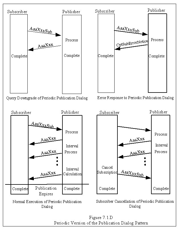
(Extended Text Description: Author’s relevant notes: Periodic Dialog Patterns. The graphic shows the systems exchanging data as rectangles on each side. The system on the left is a subscriber. The system on the right is a Scheduling System, which is a publisher. Arrows between the rectangles, like tilted rungs on a ladder, illustrate the message flows in the dialog in time sequence starting at the top. Dialog patterns define a sequence of actions in a generic format that can be reused. This example shows the operation of the Publish Subscribe Dialog Pattern. The subscriber requests information using a Query Message. In a normal execution, the publisher responds with the requested data. Depending on the content of the query, there may be a single answer or an ongoing set of answers. An ongoing set of answers is appropriate when the requested information changes on an ongoing basis (e.g., vehicle location). In an abnormal execution, the subscriber requests the information and if the publisher determines the information is unavailable, then the subscriber is not authorized. As a result, the publisher returns an error message.)
Slide 50:

Slide 51:
Learning Objective #3
Which of the following statements about data elements is correct?
Answer Choices
- A data element can include a data frame
- A data element can only include integers
- A data element cannot be used to identify a person
- A data element can be used to represent a concept
Slide 52:
Learning Objective #3
Review of Answers
a) A data element can include a data frame
Incorrect. A data frame can include a data element, but a data element cannot include a data frame.
b) A data element can only include integers
Incorrect. A data element can include several types of ASN. 1 representations.
c) A data element cannot be used to identify a person
Incorrect. A data element can be a person’s name or other identifier.
d) A data element can be used to represent a concept
Correct! A data element can represent a person, place, thing, or concept.
Slide 53:
Summary of Learning Objective #3: Identify and Provide Examples of Data Elements, Data Frames, Messages, and Dialogs
- Data Element: An atomic piece of information related to a person, place, thing, or concept
- Data Frame: Groupings of data elements and other data frames to describe more complex concepts
- Message: Aggregations of data elements and data frames into a complete, understandable, one-way communication conveying metadata and information
- Dialog: Specified sequence of messages for an operational purpose including any special conditions
- Dialog Pattern: Common forms of dialogs that can be used repeatedly for multiple purposes
Slide 54:
Learning Objective #4: Describe How Data Are Organized in TCIP Data Exchanges
- TCIP identifiers
- Optional items (fields)
- Versioning
- Row updates
- Applicability
- Local extensions
- Multilanguage support
Slide 55:
Learning Objective #4
TCIP Identifiers
-
Allow an agency to provide information about items (e.g., bus stop inventory, timepoint inventory) to an application once, and then refer to the item in subsequent messages
- For example, if we want to associate passenger count information with a bus stop, we can associate it with the identifier, and not send a complete description of the bus stop with each set of passenger counts
Slide 56:
Learning Objective #4
TCIP Identifiers (cont.)
TCIP Identifiers
-
Allow items to be uniquely identified across all transit agencies in the US
- Employees
- Intersections
- Operator bases
- Operators
- Organizational units
- Shelters
- Stop points
- Transfer clusters
- Transit facilities
- Vehicles
- Fare policies
- Fare zones
- Trips
- Incidents
- Amenities
- Announcements
- Geographic zones
- Service bulletins
- Travelers
- Blocks
- Notes
- Patterns
- Pattern segments
- Routes
- Runs
- Timepoints
- Trains
Slide 57:
Learning Objective #4
TCIP Identifiers (cont.)
-
TCIP Iden Frames ALWAYS contain:
- Alphanumeric identifier (e.g., vehicle_id)
-
TCIP Iden Frames MAY contain:
- Optional agency number
- Optional string designator that uniquely represents the item within the agency (e.g., route_designator)
- Zero or more optional string name fields for the identified item (e.g., first-name, last-name, VIN)
Slide 58:
Learning Objective #4
Optional Items (Fields)
- Support a functional requirement that is not common to all agencies (e.g., an announcement can be text, audio, or both)
- Support a capability that is only required in certain contexts (e.g., a warning in a message)
- Convey information that may or may not be available (e.g., photographs of a stoppoint)
Annex B.79 Data Frame: CPTStoppointlden {CPT 1016}
Use: Uniquely identify a stoppoint whether in a single, or multi-agency environment.
ASN.1 Representation:
CPTStoppointlden ::= SEQUENCE{
stoppoint-id CPT-StoppointID,
agency-id CPT-AgencylD OPTIONAL,
name CPT-StoppointName OPTIONAL,
nameLangs CPTAdditionalLanguageContents OPTIONAL,
designator CPT-StoppointDesignator OPTIONAL,
designatorLangs CPTAdditionalLanguageContents OPTIONAL,
agencydesignator CPT-AgencyDesignator OPTIONAL,
agencydesignatorLangs CPTAddit ionalLanguageContents OPTIONAL
}
Slide 59:
Learning Objective #4
Versioning
- Data items in TCIP need to be updated from time to time
- TCIP’s primary means of tracking versions of these items is by updating the effective date-time
- Some TCIP data items also have optional integer-based version numbers to provide backward compatibility with legacy business systems
ASN.1 Representation:
SchPatternList ::= SEQUENCE {
subscriptionInfo CPTSubscriptionHeader,
languages CPTLanguageList OPTIONAL,
patternVersion SCH-TimetableVersionID OPTIONAL,
effective CPT-DateTime,
update-sinee CPT-DateTime OPTIONAL,
update-thru CPT-DateTime,
stoppointVersion CPT-StoppointVersion OPTIONAL,
stoppointEffective CPT-DateTime,
timepointVersion SCH-TimetableVersionID OPTIONAL,
timepointEffective CPT-DateTime,
Slide 60:
Learning Objective #4
Row Updates
-
Many TCIP messages provide lists of items that can be lengthy
- Bus stops
- Timepoints
- Employees
- Vehicles
- Row updates allow changes to be sent to previously provided lists
Slide 61:
Learning Objective #4
Row Updates
Example
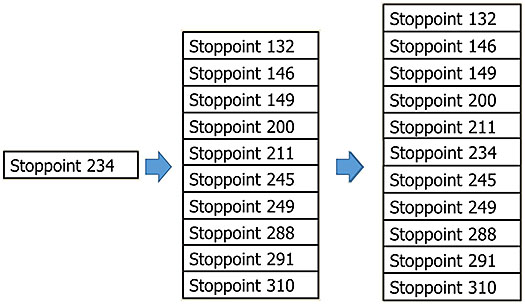
(Extended Text Description: Author’s relevant notes: This slide graphically depicts row updates. A stack of boxes in the center represents a list of stoppoints in the order they are encountered as a bus travels its route. A box to the left represents a stoppoint to be added to the route. A stack of boxes on the right represents the updated list of stoppoints with the new one inserted correctly between the preceding stoppoint and the following stoppoint.)
Slide 62:
Learning Objective #4
Row Updates (cont.)
- A message requesting row updates includes a field indicating the date-time when changes are requested
- A message providing row updates contains a field indicating the date-time that changes are provided
- A row update message may contain rows to be added, rows that replace old rows, or rows to be deleted
Slide 63:
Learning Objective #4
Applicability
- A TCIP message may contain an Applicability Field indicating the scope of the information requested or provided by that message
- Applicability Field (if present) usually occurs in the message application header
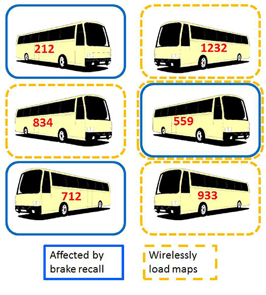
(Extended Text Description: Author’s relevant notes: This slide shows a graphic representation of TCIP applicability. Six buses, each showing an identification number, are represented in rectangles with color-coded borders. Buses in rectangles with a blue border are those for which a brake recall is applicable. Buses in rectangles with a yellow border are those for which a map update is applicable. Both the brake recall and the map update are applicable to one bus which is denoted by a rectangle with both blue and yellow borders.)
Slide 64:
Learning Objective #4
Local Extensions - Two Types
Type 1 - Code Extension
-
Adds a value to a specified enumerated list of values
-
Data Element: SCH-ServiceType {SCH-41}
- Describes the type of transit service provided
-
Local use example:
- BayFerryConnector (128) - ongoing service
- SuperBowl (129) - one time event
-
Data Element: SCH-ServiceType {SCH-41}
Slide 65:
Learning Objective #4
Local Extensions (cont.)
Type 1 - Code Extension
Local Extensions - Type 1
SCH-ServiceType ::= ENUMERATED {
regular (1), - Regular,
express (2), - Express,
circular (3), - Circular,
radial (4), - Radial,
feeder (5), - Feeder,
jitney (6), - Jitney,
limited (7), - Limited,
nonRevenue(8), - Non-revenue,
unknown (9), - Unknown,
charter (10), -- Charter Service,
school (11), -- School Service,
special (12), -- Special Service,
operatorTraining (13), - Operator Training,
maintenance (14), -- Maintenance Service,
noService (15), -- No Service,
standBy (16), -- Stand-by,
extra (17), -- Extra,
- 18-127 reserved
- 128-255 local use ... - # LOCAL_CONTENT
}
Slide 66:
Learning Objective #4
Local Extensions (cont.)
Type 2 - Frame/Message Extension
Type 2 - Frame/message extensions - add locally specified data to the sequence Data Frame: CCBlockWorkRecord
- Describe events related to work done by a PTV
CCBlockWorkRecord ::= SEQUENCE {
block SCHBIocklden,
begin-time CPT-DateTime OPTIONAL,
end-time CPT-DateTime OPTIONAL,
timepoints SEQUENCE (SIZE{1..15000)) OF CCTimepointHistorv OPTIONAL,
stoppoints SEQUENCE (SIZE{1..15000)) OF OBStoppointRecord OPTIONAL,
deviations SEQUENCE (SIZE{1..1000)) OF CCRouteDeviationRecord OPTIONAL,
passenger-miles CC-PassengerMiles OPTIONAL,
... - # LOCAL_CONTENT
}
- Local use example:
dailySamples SEQUENCE(SIZE(1.. 1000)) OF ABCAirQualitySample OPTIONAL
Slide 67:
Learning Objective #4
Multilanguage Support
- TCIP can support multiple languages, beginning with TCIP version 3.0.4
- Languages are specified using ISO 639 codes
-
"CPTLanguageList" data frame specifies the default and additional languages
- Optional item
- Where string content appears in a message, "CPTAdditionalLanguageContent" data frames provide the information in the additional languages
Slide 68:

Slide 69:
Learning Objective #4
Which statement best characterizes a TCIP identifier?
Answer Choices
- Uses a shorthand code to represent an item
- Identifies a TCIP-generated message
- Identifies a unique data frame
- Always includes a string designator to identify an item
Slide 70:
Learning Objective #4
Review of Answers
a) Uses a shorthand code to represent an item
Correct! A TCIP identifier can be used to represent an item that may have a longer description.
b) Identifies a TCIP-generated message
Incorrect. A TCIP identifier represents items in the real world, not TCIP elements.
c) Identifies a unique data frame
Incorrect. A TCIP identifier would not be used to represent a TCIP data frame. An identifier is a data element.
d) Always includes a string designator to identify an item
Incorrect. String designators are optional types of identifiers; alpha-numeric identifiers are mandatory.
Slide 71:
Summary of Learning Objective #4:
Describe How Data Are Organized in TCIP Data
Exchanges
TCIP Provides a Way To:
- Create unique identifiers for information across all transit agencies
- Identify version of information provided
- Incrementally update large data sets
- Define and use groups of items/entities
- Include locally defined data in TCIP messages
Slide 72:
Learning Objective #5: Define a Profile Requirements List (PRL) and Explain How It Is Used to Specify TCIP Requirements in a Transit ITS Project
- Profile Information
- Component selection
- Interface definition
- Interface tailoring
- Document creation
Slide 73:
Learning Objective #5
Profile Information
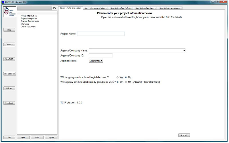
(Extended Text Description: Author’s relevant notes: Profile information entry is in the first tab of TIRCE. As can be seen from the screen shot, TIRCE asks the user to enter a name for the project, agency/company name and ID, and asks if the profile is for a single or multiple agency model architecture. It also asks the user if languages other than English will be used and if agency-defined applicability groups will be used.)
Slide 74:
Learning Objective #5
TIRCE Example - Component Selection
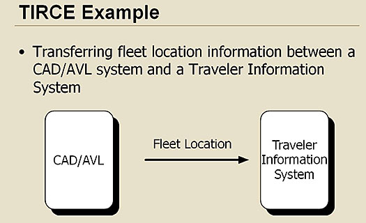
(Extended Text Description: This slide includes a graphic representation of two components which will exchange information using TCIP. A rectangle on the left represents a CAD/AVL system. A rectangle on the right represents a Traveler Information System. An arrow labeled "Fleet Location" points extends from the CAD/AVL system toward the Traveler Information System, representing the flow of information. A text bullet reads, Transferring fleet location information between a CAD/AVL system and a Traveler Information System.)
Slide 75:
Learning Objective #5
TIRCE Example - Component Selection
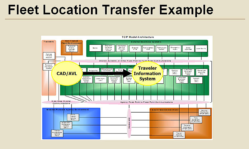
(Extended Text Description: TCIP Model Architecture. The graphic on this slide illustrates the TCIP Model Architecture with various areas where subsystems are located and the communication links between subsystems. It shows how components can be selected directly from this graphic which is included in the TIRCE tool. At the top is a box that includes External Business Systems. Immediately below that is a box that includes Transit Business Systems. These areas indicate systems that are located in an office and don’t move around (e.g., Banks, Data Repositories, Transit Security, CAD/AVL). Below and to the right of the Transit Business Systems box is a box representing Transit Field Environment. This area indicates systems that are not in an office, but they don’t move around either (e.g., bus stop, station, TVM, kiosk). Above and to the left of the Transit Business Systems box is a box for Non-Transit Field Environment. This area indicates systems that are not in an office, but they don’t move around AND they are not related to transit (specifically) (e.g., traffic lights). To the left of the Transit Business Systems box is a box representing the Travelers. Below and to the left of the Transit Business Systems box is a box which includes Mobiles/Portable Agency Environment. This area indicates systems that move (e.g., vehicles). Between each box is a narrow oval, like a sausage, that depicts the communications links among the various types of systems, including fixed-point communications between stationary elements and wireless communications to elements that move. In this example, the CAD/AVL system and the Traveler Information System are the components selected to exchange information.)
Slide 76:
Learning Objective #5
TIRCE Example - Interface Definition and Tailoring
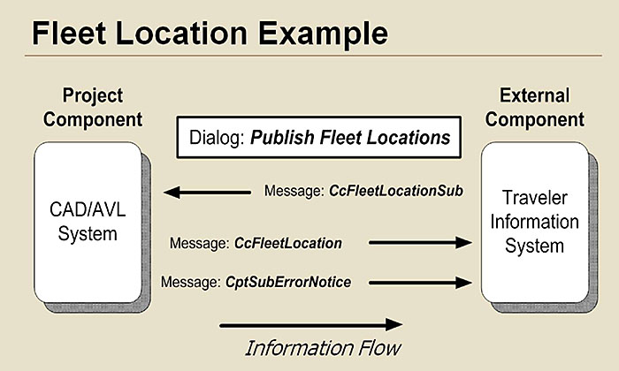
(Extended Text Description: Author’s relevant notes: The graphic in this slide uses a diagram similar to slide #74, with the CAD/AVL system shown as a rectangle on the left and the Traveler Information System shown as a rectangle on the right. The graphic illustrates the TCIP dialog: Publish Fleet Locations. A horizontal arrow pointed toward the left represents the first message in the dialog, "CcFleetLocationSub" from the Traveler Information System subscribing to the CAD/AVL. A horizontal arrow below that pointing to the right represents the second message in the dialog, CcFleetLocation" which is sent from the CAD/AVL to the Traveler Information System. A third horizontal arrow below that pointing toward the right represents an alternate message "CptSubErrorNotice," which is an error message sent if the fleet location data is not available.)
Slide 77:
Learning Objective #5
TIRCE Example - Document Creation
| Profile Requirements List (PRL) Cover Sheet | |||
| Project Name: abc | |||
| Creation Date: August 17,2014 | |||
| Agency/Company Name: abc | |||
| Agency ID: | |||
| Agency Model: Unknown | |||
| Project Component(s): Computer Aided Dispatch/ Automatic Vehicle Location | |||
| External Component(s): Traveler Information System | |||
| Profile Requirements List (PRL) | |||
| Project Name: abc | |||
| Agency/Company Xaue: abc | Agency ID: | Agency Model: Unknown | |
| Project Component: | IP/Network Address: | Port/Transport Address: | |
| Computer Aided Dispatch. Automatic Vehicle Location | CAD_AVL | CAD_AVL_PORT | |
| External Component: | lP/Network Address: | Port/Transport Address: | |
| Traveler Information System | TIS | TIS_PORT | |
| Non TCIP Interfaces Supported: | |||
| Exceptions to TCIP Requirements: | |||
| Conformance Class 1A: Supported Dialogs | |||
| Project Component: Computer Aided Dispatch/Automatic Vehicle Location | |||
| Externa] Component: Traveler Information System | |||
| Dialog Name | Role | TCIP Version | PRL Annex |
| Publish Fleet Locations | Publisher | 3.0.6 | 1.A.1 |
| Conformance Class 2A: TCIP Message Files Accepted | |||
| Project Component: Computer Aided Dispatch/Automatic Vehicle Location | |||
| External Component: Traveler Information System | |||
| File Attributes & limitations: | |||
Slide 78:
Learning Objective #5
Example of XML-Encoded TCIP Message
Produced by TIRCE for a PRL
I version="1.0" encoding="UTF-8"?>
ccLocationReport sourceport = "62627" sourceip = "192.168.0.65"created = "2013-04-24T17:17:29.960Z" sourcea _Final_3_0_4.xsd" xmlns:local="http://www.tcip-3-0-4-local" xmlns:tcip="http://www.TCIP-Final-3-0-4" i :xsi="http://www.w3.org/200I/XMLSchema-instance" >
request-id >4001</request-id >
status-info>3</status-info>
time-reported >2016-01-07T13:10:23</time-reported>
latitude>31000000</latitude>
longitude>-89000000</longitude>
- <direction>
<deg>90</deg>
<rad>0</rad>
<cdeg>0</cdeg>
</direction>
<speed>50</speed>
</tcip: ccLocationReport >
Slide 79:

Slide 80:
Learning Objective #5
Which of the following is not included in the preparation of a Profile Requirements List (PRL)?
Answer Choices
- Profile information
- Component selection
- Vendor conformance
- Interface tailoring
Slide 81:
Learning Objective #5
Review of Answers
a) Profile information
Incorrect. Profile information is included in a PRL.
b) Component selection
Incorrect. Component selection is included in a PRL.
c) Vendor conformance
Correct! Vendor conformance is not included in preparing a PRL. The DIFF function would be used.
d) Interface tailoring
Incorrect. Interface tailoring is used in preparation of a PRL.
Slide 82:
Summary of Learning Objective #5: Define a Profile Requirements List (PRL) and Explain How It Is Used to Specify TCIP Requirements in a Transit ITS Project
- Profile information includes entering data to describe the project and identify the agency developing the profile
- Component selection involves choosing the subsystems that will exchange data
- Interface definition involves selecting the file transfers and dialogs
- Tailoring involves selecting specific messages to be exchanged
- Document creation involves producing the Profile Requirements List (PRL) specifications and XML schema
Slide 83:
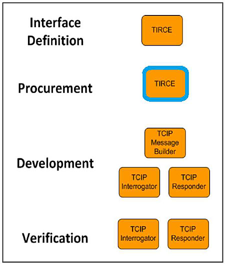
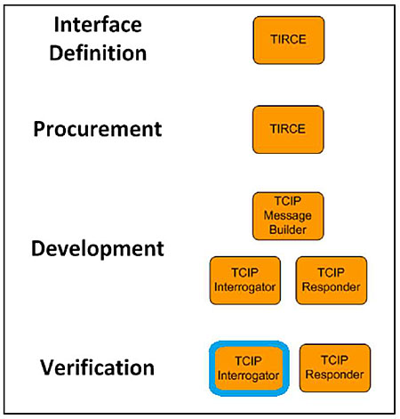
Learning Objective #6: Articulate and Describe the Uses of Each Tool in the TCIP Suite of Tools
- Interface Definition - TIRCE
- Procurement -TIRCE
- Development -Message Builder, Interrogator, Responder
- Verification - Interrogator, Responder
Slide 84:
Learning Objective #6
TCIP Tool Suite
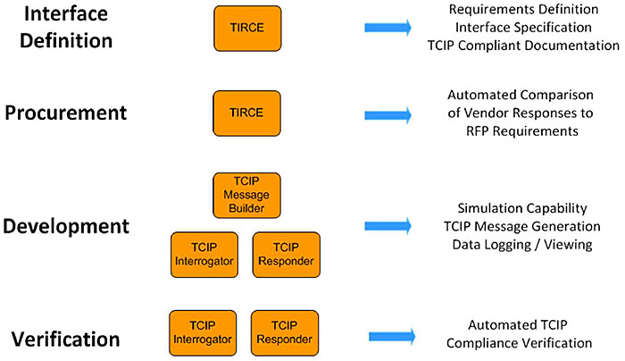
(Extended Text Description: Author’s relevant notes: TCIP Support Tools Suite. This slide shows items in three columns which illustrate the typical sequence in which TCIP tools are used and the purpose of each. Column one shows stages in the process. Column two show boxes labeled with the TCIP tools that are used. Column three shows the capability provided by each tool in the sequence. Starting at the top: "Interface Definition" is accomplished using the tool "TIRCE" which produces "Requirements Definition," Interface Specification, "and TCIP Compliant Documentation." The second stage, "Procurement," is accomplished using the tool "TIRCE" which produces an "Automated Comparison of Vendor Responses to RFP Requirements." The third stage, "Development," uses three TCIP tools, "TCIP Message Builder," TCIP Interrogator," and "TCIP Responder." These tools provide "Simulation Capability," TCIP Message Generation," and Data Logging/Viewing". The fourth stage, "Verification," uses the tool "TCIP Interrogator" which produces an "Automated TCIP Compliance Verification.")
Slide 85:
Learning Objective #6
Uses of TCIP Tools: Interface Definition -
TIRCE
TIRCE Allows a User to Specify an Interface in Five Steps
- Specify profile information
- Select components
- Define interfaces
- Tailor interfaces
- Produce documents
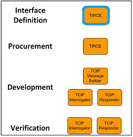
(Extended Text Description: This slide uses the diagram shown in Slide #84 with the top box labeled "TIRCE" highlighted.)
Slide 86:
Learning Objective #6
Uses of TCIP Tools: Procurement - TIRCE
TIRCE Produces Two Key Documents to Facilitate ITS Procurements
- Profile Requirements List (PRL)
- Profile Implementation Conformance Statement (PICS)
-
TIRCE provides a Diff function:
- To compare agency requirements (PRL)
- With vendor product specifications (PICS)
(Extended Text Description: This slide uses the diagram shown in Slide #84 with the second box labeled "TIRCE" highlighted)
Slide 87:
Learning Objective #6
Uses of TCIP Tools - Development
TCIP Message Builder
- Enables user to generate XML-encoded TCIP messages
- Messages are used by the TCIP Test Console applications
- Load / save / view / edit TCIP messages
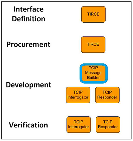
(Extended Text Description: This slide uses the diagram shown in slide #84 with the box labeled "TCIP Message Builder" highlighted.)
Slide 88:
Learning Objective #6
TCIP Message Builder - Example
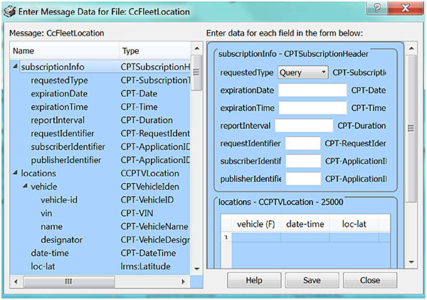
(Extended Text Description: Author’s relevant notes: This screenshot of the message builder illustrates how users can create a test message to test the specification.)
Slide 89:
Learning Objective #6
Uses of TCIP Tools - Verification
TCIP Test Console
- Provides capability to simulate one, or both, ends of a TCIP interface
-
Consists of two functions:
- TCIP Interrogator -> requests TCIP data
- TCIP Responder -> supplies TCIP data
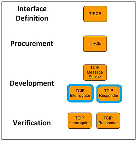
(Extended Text Description: This slide uses the diagram shown in slide #84 with the boxes labeled "TCIP Interrogator" and "TCIP Responder" highlighted.)
Slide 90:
Learning Objective #6
Uses of TCIP Tools - Verification (cont.)
TCIP Interrogator
-
Simulates a TCIP-compliant device
- Client side of interface
- Subscribes to a provider (publisher) of TCIP data
- Establishes a TCIP communications link with a TCIP device under development or test
- Transmits/receives TCIP messages
- View/log TCIP messages
- Automated TCIP message verification
(Extended Text Description: This slide uses the diagram shown in Slide #84 with the lower box labeled "TCIP Interrogator" highlighted.)
Slide 91:
Learning Objective #6
Uses of TCIP Tools - Verification (cont.)
TCIP Responder
-
Simulates a TCIP-compliant device
- Server side of interface
- Provides TCIP data upon receipt of a subscription request
-
Data are preloaded
- Previously created (via TCIP Message Builder) or recorded TCIP messages
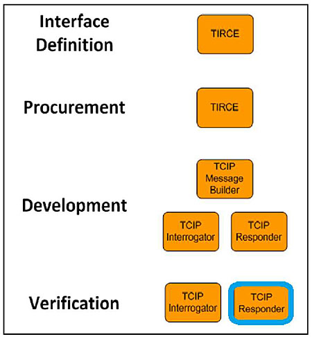
(Extended Text Description: This slide uses the diagram shown in Slide #84 with the lower box labeled "TCIP Responder" highlighted.)
Slide 92:
Learning Objective #6
TCIP Tool Suite - Test Console
Testing a Component
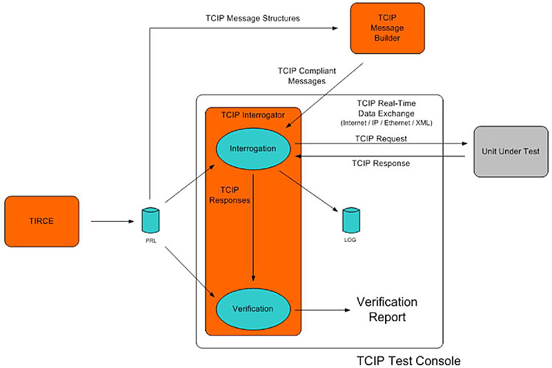
(Extended Text Description: This diagram illustrates the logical structure of the TCIP test console. A box on the left labeled "TIRCE" represents using TIRCE to create a PRL, which is shown as a cylindrical data file. An arrow representing TCIP message structures originates from the PRL and points to a box at the top labeled "TCIP Message Builder." An arrow from the message builder points toward a box labeled "TCIP interrogator" and represents the content of TCIP compliant messages. To the right of the PRL is the rectangle which represents the TCIP interrogator. Two other arrows from the PRL point respectively at ovals inside the interrogator box, labeled "interrogator" and "verification." These arrows represent TCIP message structures used to initiate and verify that a unit under test, represented by a rectangle to the right of the interrogator box, is responding correctly to a TCIP data request from the interrogator.)
Slide 93:
Learning Objective #6
TCIP Tool Suite - Test Console
Testing a Simulated Component
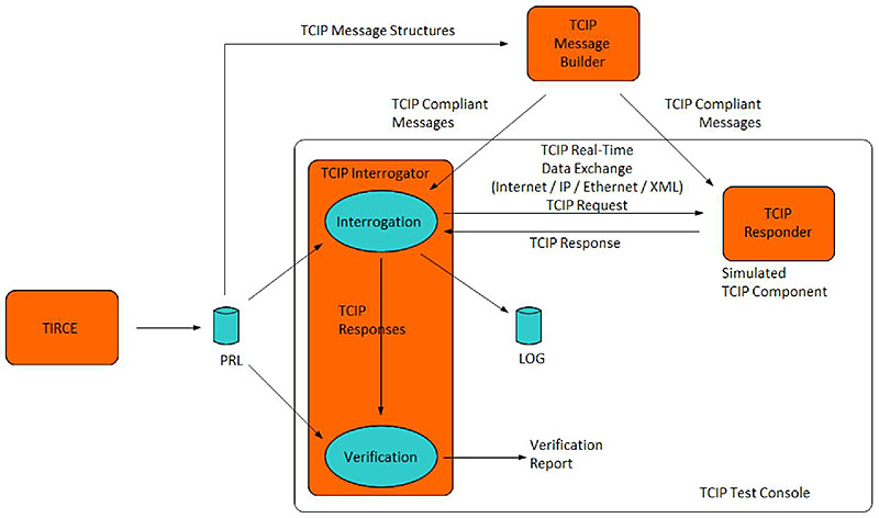
(Extended Text Description: Author’s relevant notes: This diagram illustrates how the test console can be used to simulate both sides of an interface between components and is related to Slide #92. The box labeled "unit under test" is replaced with a rectangle labeled "TCIP responder" and the message builder has an additional arrow pointing to the "TCIP Responder" showing that the message builder is supplying test messages to the responder.)
Slide 94:

Slide 95:
Learning Objective #6
Which of the following statements about the underlined TCIP tool function is FALSE?
Answer Choices
- Interrogator simulates a client component requesting data
- Responder simulates a server providing data
- Test Console corrects errors in XML schema
- TIRCE (Diff function) compares a PICS with a PRL
Slide 96:
Learning Objective #6
Review of Answers
a) Interrogator simulates a client component requesting data
Incorrect. This statement is true.
b) Responder simulates a server providing data
Incorrect. This statement is true.
c) Test Console corrects errors in XML schema
Correct! This statement is false. The test console does not correct XML errors.
d) TIRCE (Diff function) compares a PICS with a PRL
Incorrect. This statement is true.
Slide 97:
Summary of Learning Objective #6: Articulate and Describe the Uses of Each Tool in the TCIP Suite of Tools
- TCIP Implementation, Requirements and Capabilities Editor (TIRCE) can be used to specify interfaces between components
- TIRCE also can be used to prepare procurement documents representing the agency view, Profile Requirements List (PRL), and vendor’s view, Profile Implementation Conformance Statement (PICS)
- TCIP Message Builder can be used to construct TCIP-compliant messages using XML. Messages can be saved, viewed, and edited.
- TCIP Test Console can simulate one or both ends of a TCIP interface. It includes an interrogator, which simulates the client side of the data exchange, and a responder to simulate the server side of the data exchange
Slide 98:
Learning Objective #7: Summarize the Range of TCIP Applications, Implementation Tools, and Additional Training
- Non-normative TCIP content - model architecture and concept of operations
- Normative TCIP content - building blocks, data elements to dialogs
- Implementation tools
- Examples of TCIP implementation at transit agencies
- Overview of National Transit Institute (NTI) on-site training for TCIP
Slide 99:
Learning Objective #7
Non-Normative TCIP Content - Model Architecture and Concept of Operations
-
TCIP contains non-normative material that has not been balloted but is useful as context for applying the standard. The following items are non-normative:
- TCIP Model Architecture
- TCIP Concept of Operations
Slide 100:
Learning Objective #7
Non-Normative TCIP Content - Model Architecture and Concept of Operations (cont.)
Where do I find it?
-
American Public Transportation Association (APTA)
- Transit Communications Interface Profiles (TCIP) Standard Development Program
- APTA-TCIP-S-01 4.0 Volume I
How do I get it?
- Download FREE from:
Slide 101:
Learning Objective #7
Normative TCIP Content - Building Blocks, Data Elements to Dialogs
Where do I find it?
- TCIP 4.0 Volume I - Basis for conformance
-
TCIP 4.0 Volume II - Data and Dialog Definitions
- Annex A -TCIP Data Elements
- Annex B - TCIP Data Frames
- Annex C - TCIP Messages
- Annex D - TCIP Dialogs
-
TCIP 4.0 Volume III - TCIP XML Schema
- Annex E -TCIP XML Schema
Slide 102:
Learning Objective #7
TCIP Implementation Tools
- TIRCE
- Message Builder
- Test Console
Where do I get them?
- Transit Communications Interface Profiles (TCIP) Standard Development Program APTA-TCIP TIRCE & Support Tools and Support Tool Installation Instructions
Download FREE from:
Slide 103:
Learning Objective #7
TCIP Tools Download - Implementation Tools
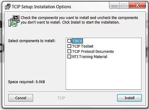
(Extended Text Description: Author’s relevant notes: This graphic shows the TCIP Window. Users can download all tools at once, including example protocol documents and training examples from the NTI course on TCIP.)
Slide 104:
Learning Objective #7
TCIP Tools Download - Implementation Tools
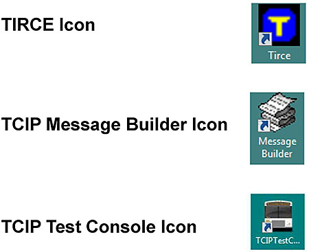
(Extended Text Description: Author’s relevant notes: This graphic shows the desktop icons for each of the TCIP tools: TIRCE, Message Builder, and Test Console.)
Slide 105:
Learning Objective #7
Who Is Using TCIP? Examples and Real World Applications
Current TCIP Projects
- LYNX (Orlando)
- King County Metro (Seattle)
- New York MTA (NYC)
- AMT (Montreal)
- WMATA (Washington DC)
- DART (Dallas)
Slide 106:
Learning Objective #7
Examples of TCIP Implementation at Transit Agencies
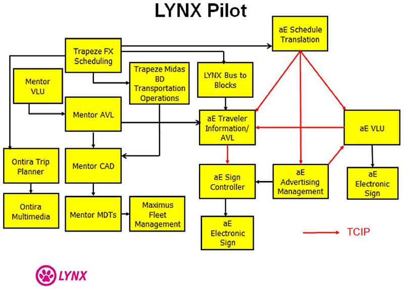
(Extended Text Description: Author’s relevant notes: Who is using TCIP? Examples and Real World Applications – Lynx Pilot. This slide shows a snapshot of the FUTURE LYNX (Orlando) Agency ITS Architecture. Non-TCIP interfaces are shown by black lines connecting the boxes. TCIP interfaces are shown by red lines. Descriptions for non-generic boxes in the LYNX Architecture Trapeze Scheduling is a Transit Schedule Development Platform. This system provides data to Trapeze BD and to aE Schedule Translation which uses TCIP to interface with aE Traveler Information/AVL, aE Advertising Manager and aE VLU. Trapeze BD Transportation Operations provides bid processing, dispatch control, and timekeeping and sends data to Mentor CAD. Mentor AVL provides near-real time bus tracking data to Mentor CAD and to aE Traveler Information/AVL. Mentor CADD provides computer assisted management of buses while they are en route as well as for initial dispatch. LYNX Bus to Blocks is a LYNX IT Application that manages the daily assignment of buses to blocks (work assignments) which also provides information to aE Traveler Information/AVL. Ontira Trip Planner provides customers with address-to-address trip planning by combining a routing algorithm with dynamic mapping and provides data to Ontira Multimedia which provides customers with service information via a variety of communications media (phones, internet, kiosks, etc.).)
Slide 107:
Learning Objective #7
Examples of TCIP Implementation at Transit Agencies (cont.)
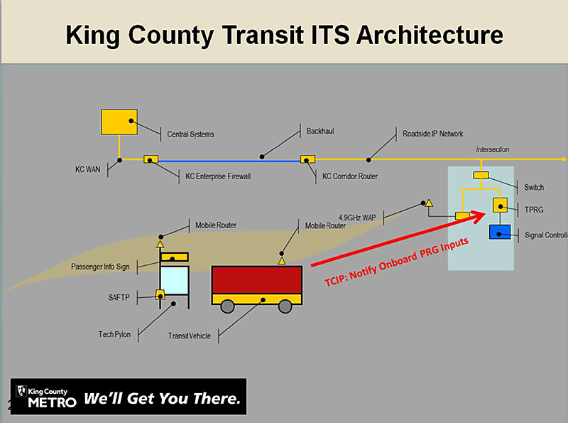
(Extended Text Description: Author’s relevant notes: Who is using TCIP? Examples and Real World Applications (cont.) – King County Transit ITS Architecture. This graphic shows the King County Metro architecture for Transit Signal Priority. TCIP will be used to communicate information that supports signal priority requests from buses to the traffic signal control system. The TCIP compliant interface is shown as a red line. The conversation between the Priority Request Generator (PRG) and the Priority Request Server (PRS) uses a different standard.)
Slide 108:
Learning Objective #7
Examples of TCIP Implementation at Transit Agencies (cont.)
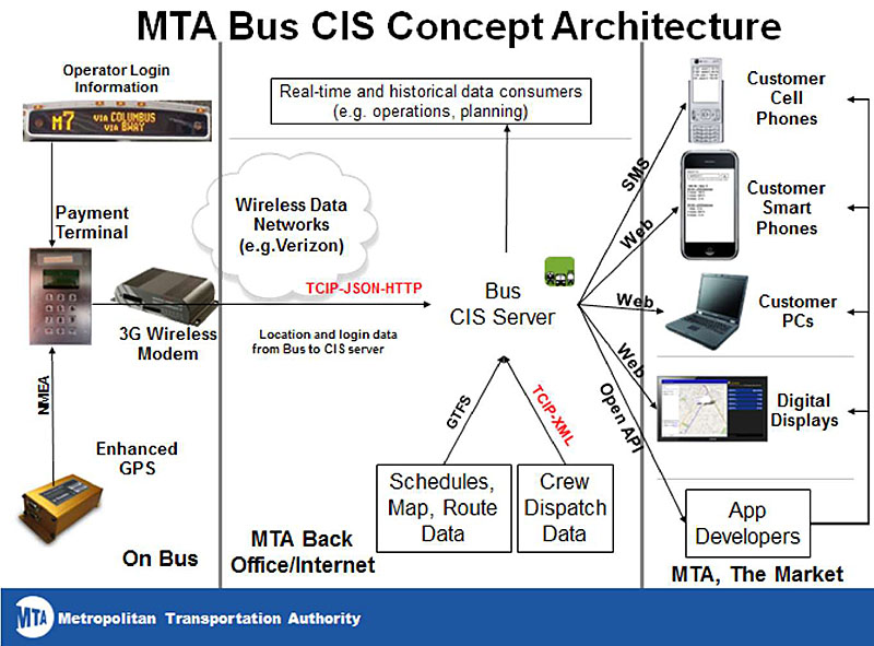
(Extended Text Description: Author’s relevant notes: Who is using TCIP? Examples and Real World Applications (cont.) – MTA Bus Time Technology – MTA Bus CIS Concept Architecture. This graphic illustrates the New York MTA’s bus customer information system architecture. TCIP is used in conjunction with other standards to communicate real time bus arrival data every 30 seconds from 5,500 buses to the central server. On the left are shown components on a bus, including the Operator Login Information which is sent to the Payment Terminal. An enhanced GPS unit provides NEMA standard location data to the Payment Terminal which then sends location and login data from the bus to a 3G modem. The Verizon wireless data network sends the data which uses standards including TCIP, JSON and HTTP to the CIS server in the MTA back office. Here, GTFS standard is used to send Schedules, Map and Route Data to the Bus CIS Server. TCIP is used to send crew dispatch data to the Bus CIS Server. The Bus CIS Server uses SMS to send information to customer cell phones, and uses the web to send data to smart phones, customer PC’s, and digital displays.)
Slide 109:
Learning Objective #7
Examples of TCIP Implementation at Transit Agencies (cont.)
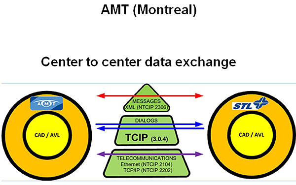
(Extended Text Description: Author’s relevant notes: Who is using TCIP? Examples and Real World Applications (cont.) AMT Montreal. This graphic illustrates how Montreal’s Agence Métropolitaine de Transport (AMT) uses TCIP dialogs to exchange data between two different CAD/AVL servers. A CAD/AVL Server for AMT is shown as a circle on the left. This exchanges data over a communications stack depicted as a triangle in the middle. On the right, a circle represents the CAD/AVL server for a sister agency, STL. The triangle segments in the middle illustrate the communication layers involved the exchange. Ethernet protocols are the bottom layer. TCIP is the next layer which is used to specify the dialogs. The messages in the dialogs are encoded in XML using the TCIP schema shown as the top layer.)
Slide 110:
Learning Objective #7
Examples of TCIP Implementation at Transit Agencies (cont.)
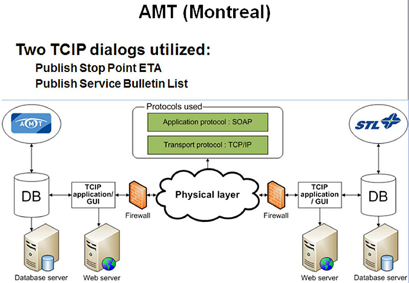
(Extended Text Description: Author’s relevant notes: This slide illustrates in greater detail the interface between AMT and STL servers in Montreal. On the left, a cylinder represents the AMT database. A two-way arrow represents the information flow between the database and a TCIP application and graphic user interface which sends information to a web server. The TCIP application exchanges TCIP encoded information through a firewall to an Ethernet connection, and then through a firewall to a similar configuration on the right representing the STL end of the link. Boxes above the Ethernet link graphically depict the communications stack protocols used, including SOAP in the application layer and TCP/IP in the transport layer.)
Slide 111:
Learning Objective #7
Examples of TCIP Implementation at Transit Agencies (cont.)
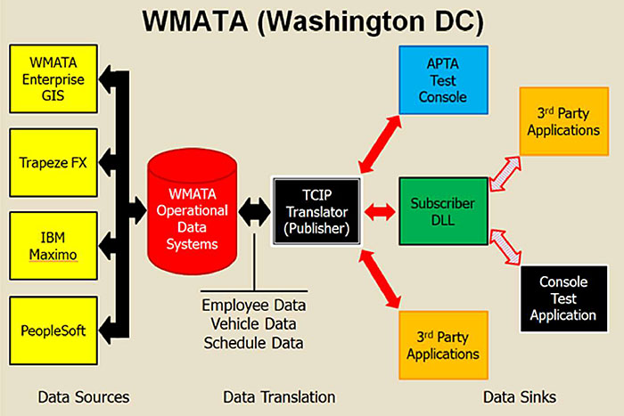
(Extended Text Description: Author’s relevant notes: This slide graphically shows the WMATA TCIP pilot. TCIP is used to translate data from legacy systems and publish data to 3rd party systems.
On the left are four boxes stacked vertically. From the top down, the boxes are labeled respectively: "WMATA Enterprise GIS," "Trapeze FX," IBM Maximo," and "PeopleSoft." These four boxes exchange data with a cylinder to the right labeled "WMATA Operational Data Systems." To the right of the cylinder is a box labeled "TCIP Translator (Publisher)" which exchanges Employee Data, Vehicle Data, and Schedule Data with the WMATA Operational Data Systems. In turn, the TCIP Translator exchanges data with three boxes to the right, respectively representing "APTA Test Console," Subscriber DLL," and "3rd Party Applications." The subscriber DLL exchanges data with two additional boxes to the right, respectively labeled "3rd Party Applications and "Console Test Application.")
Slide 112:
Learning Objective #7
National Transit Institute Course
Integrating Transit Applications: Defining Data Interfaces Using TCIP
- The National Transit Institute offers a two-day course
- Covers material presented in both TCIP online modules
- Provides hands-on instruction
- Register at www.ntionline.com
Slide 113:

Slide 114:
Learning Objective #7
Which one of the following lists includes only normative elements of TCIP?
Answer Choices
- Dialogs, TIRCE, model architecture
- TIRCE, dialogs, XML schema
- Dialogs, XML schema, data elements
- Model architecture, dialogs, XML schema
Slide 115:
Learning Objective #7
Review of Answers
a) Dialogs, TIRCE, model architecture
Incorrect. Model architecture is non-normative.
b) TIRCE, dialogs, XML schema
Incorrect. TIRCE is non-normative.
c) Dialogs, XML schema, data elements
Correct! Dialogs, XML schema, and data elements are all normative.
d) Model architecture, dialogs, XML schema
Incorrect. Model architecture is non-normative.
Slide 116:
Summary of Learning Objective #7: Summarize the Range of TCIP Applications, Implementation Tools, and Additional Training
- TCIP contains both normative and non-normative information in four volumes
- TCIP includes a set of tools to implement the standard using XML schema
- TCIP documents and tools can be downloaded FREE from APTA’s website
- A number of transit agencies are using TCIP in a variety of ways
- National Transit Institute (NTI) offers a two-day on-site TCIP training course
Slide 117:
What We Have Learned
- TCIP is used in the top layer of the "communications stack."
- The TCIP Implementation, Requirements and Capabilities Editor_(TIRCE)_ is a key tool for use in transit ITS procurements.
- TCIP building blocks include data elements, data frames, messages, and dialogs_.
- Messages are the highest level for TCIP-encoded data in file transfers and dialogs.
- A Profile Requirements List (PRL) is used to specify an agency’s TCIP requirements in a transit ITS project.
- The TCIP suite of tools includes: TIRCE , message builder, interrogator, and responder.
Slide 118:
Resources
- APTA TCIP-S-001 4.0.0, APTA Draft Standard for Transit Communications Interface Profiles, https://www.aptatcip.com/Documents.htm- content is no longer available.
- Concept of operations - Wikipedia, the free encyclopedia
- ITS PCB T3 Webinars on ITS Transit Standards t3 archives.aspx
- "Integrating Transit Applications: Defining Data Interface Requirements Using TCIP - Participant Workbook"
- "J. Fayos, draft "NTI Instructor Materials: Integrating Transit Applications: Defining Data Interfaces Using TCIP," NTI, August, 2013
- NTI Instructor Materials: Integrating Transit Applications: Defining Data Interfaces Using TCIP," Power Point Presentation, NTI, February, 2012
Slide 119:
Next Course Modules
Students who have completed Module 4 may delve into the following PCB modules:
- Module 5: Transit Management Standards, Part 2 of 2
- Module 7: Traveler Information, Part 2 of 2
- Module 9: Arterial Management & Transit Signal Priority, Part 2 of 2
- Module 10: Electronic Fare Payment Systems
- Module 11: Transit and the Connected Vehicle Environment / Emerging Technologies, Applications, and Future Platforms
Slide 120:
Thank you for completing this module.