ITS Transit Standards Professional Capacity Building Program
Module 7: Traveler Information Standards, Part 2 of 2
HTML of the PowerPoint Presentation
(Note: This document has been converted from a PowerPoint presentation to 508-compliant HTML. The formatting has been adjusted for 508 compliance, but all the original text content is included, plus additional text descriptions for the images, photos and/or diagrams have been provided below.)
Slide 1:
(Extended Text Description: Welcome - Graphic image of introductory slide. A large dark blue rectangle with a wide, light grid pattern at the top half and bands of dark and lighter blue bands below. There is a white square ITS logo box with words "Standards ITS Training" in green and blue on the middle left side. The word "Welcome" in white is to the right of the logo. Under the logo box is the logo for the U.S. Department of Transportation, Office of the Assistant Secretary for Research and Technology.)
Slide 2:
(Extended Text Description: This slide, entitled "Mac Lister" has a photo of Mac Lister, Program Manager Knowledge and Technology Transfer, ITS Joint Program Office, on the left hand side, with his email address, Mac.Lister@dot.gov. A screen capture snapshot of the home webpage is found on the right hand side - for illustration only - from August 2014. Below this image is a link to the current website: www.its.dot.gov/pcb - this screen capture snapshot shows an example from the Office of the Assistant Secretary for Research and Development - Intelligent Transportation Systems Joint Program Office - ITS Professional Capacity Building Program/Advanced ITS Education. Below the main site banner, it shows the main navigation menu with the following items: About, ITS Training, Knowledge Exchange, Technology Transfer, ITS in Academics, and Media Library. Below the main navigation menu, the page shows various content of the website, including a graphic image of professionals seated in a room during a training program. A text overlay has the text Welcome to ITS Professional Capacity Building. Additional content on the page includes a box entitled What’s New and a section labeled Free Training. Again, this image serves for illustration only. The current website link is: https://www.its.dot.gov/pcb.)
Slide 3:
(Extended Text Description: This slide, entitled "Jeffrey Spencer" has a photo of Jeffrey Spencer, ITS Team Leader, Federal Transit Administration, Office of Research, Demonstration and Innovation, on the left hand side, with his email address, Jeffrey.Spencer@dot.gov. A screen capture snapshot of the home webpage is found on the right hand side - for illustration only - which is the same screen snapshot from Slide 2. Below this image and to the right is the Federal Transit Administration (FTA) logo.)
Slide 4:

Slide 5:
ITS Transit Standards Professional Capacity Building Program
Module 7:
Traveler Information Standards, Part 2 of 2
Slide 6:
Instructor

Carol L. Schweiger
President
Schweiger Consulting LLC
Wakefield, MA, USA
Slide 7:
Target Audience
- Transit agency technical staff from the planning, customer information, and information technology areas/departments
- Regional (multi-modal) Traveler Information System technical manager (at transit, State Department of Transportation, Metropolitan Planning Organization, etc.)
- Technology vendors and consultants
- Application developer community
- Transit or transportation agency procurement and grants staff (optional)
Slide 8:
Recommended Prerequisite(s)
| Decision-Maker | Project Manager | Project Engineer | |
|---|---|---|---|
| Module 1: Introduction to ITS Transit Standards | N/A | ✓ | ✓ |
| Module 2: Transit Management Standards, Part 1 of 2 | N/A | ✓ | ✓ |
| Module 3: Transit Communications Interface Profiles (TCIP), Part 1 of 2 | N/A | ✓ | ✓ |
| Module 4: Transit Communications Interface Profiles (TCIP), Part 2 of 2 | N/A | ✓ | ✓ |
| Module 5: Transit Management Standards, Part 2 of 2 | N/A | ✓ | ✓ |
| Module 6: Traveler Information, Part 1 of 2 | IM/A | ✓ | ✓ |
Slide 9:
Recommended Prior Knowledge
- Basic understanding of transit-related portions of the National ITS Architecture
- Detailed understanding of how traveler information is generated and disseminated
- Detailed understanding of the technology that is used in providing traveler information
- Basic knowledge of systems engineering, which can be obtained from NTI’s course entitled Systems Engineering for Transit ITS Projects
Slide 10:
Curriculum Path (Project Manager)
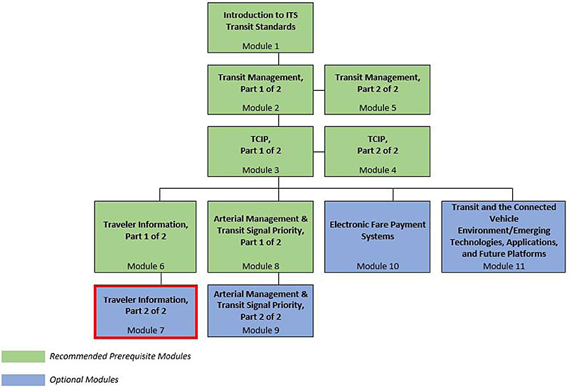
(Extended Text Description: Curriculum Path for Project Manager: A graphical illustration indicating the sequence of training modules and where this module fits in. Each module is represented by a box with the name of the module in it and a flow chart showing the logical flow of the modules with the current module boxed in red. The first three vertically sequenced boxes are green, which means that it is a Recommended Prerequisite Module. The first box is "Introduction to ITS Transit Standards, Module 1." Below that, connected by a line, is a box with the text "Transit Management, Part 1 of 2." To the right of this box, is "Transit Management, Part 2 of 2." Below "Transit Management, Part 1 of 2", connected by a line, is a box with the text "TCIP, Part 1 of 2." To the right of this box, is "TCIP, Part 2 of 2." Below "TCIP, Part 1 of 2," the lines branch out into four boxes that are horizontally sequenced. The first two: "Traveler Information, Part 1 of 2" and "Arterial Management & Transit Signal Priority, Part 1 of 2" are green; the other two: "Electronic Fare Payment Systems," and "Transit and the Connected Vehicle Environment/Emerging Technologies, Applications, and Future Platforms" are blue. Blue indicates that the module is optional. Below "Traveler Information, Part 1 of 2," is the text box "Traveler Information, Part 2 of 2 coded in blue and outlined in red. Below "Arterial Management & Transit Signal Priority, Part 1 of 2", is the text box "Arterial Management & Transit Signal Priority, Part 2 of 2," coded in blue.)
Slide 11:
Curriculum Path (Project Engineer)
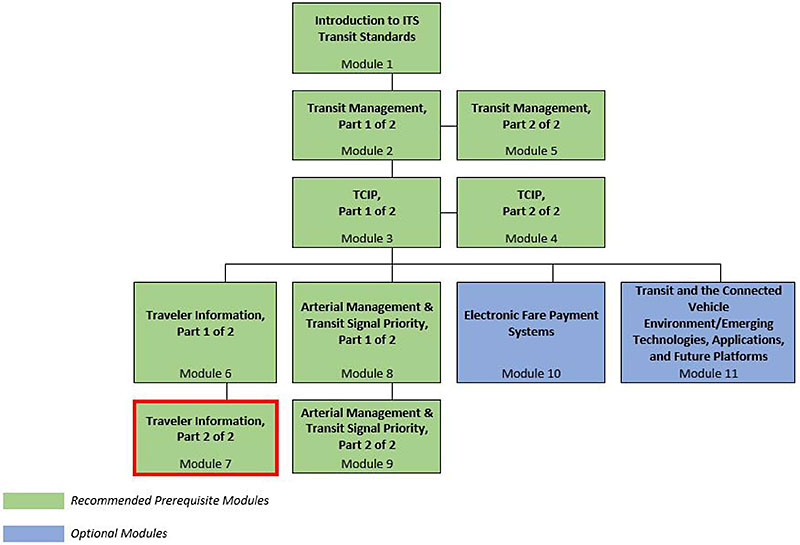
(Extended Text Description: Curriculum Path for Project Engineer: A graphical illustration indicating the sequence of training modules and where this module fits in. Each module is represented by a box with the name of the module in it and a flow chart showing the logical flow of the modules with the current module boxed in red. The first three vertically sequenced boxes are green, which means that it is a Recommended Prerequisite Module. The first box is "Introduction to ITS Transit Standards, Module 1." Below that, connected by a line, is a box with the text "Transit Management, Part 1 of 2." To the right of this box, is "Transit Management, Part 2 of 2." Below "Transit Management, Part 1 of 2", connected by a line, is a box with the text "TCIP, Part 1 of 2." To the right of this box, is "TCIP, Part 2 of 2." Below "TCIP, Part 1 of 2," the lines branch out into four boxes that are horizontally sequenced. The first two: "Traveler Information, Part 1 of 2" and "Arterial Management & Transit Signal Priority, Part 1 of 2" are green; the other two: "Electronic Fare Payment Systems," and "Transit and the Connected Vehicle Environment/Emerging Technologies, Applications, and Future Platforms" are blue. Blue indicates that the module is optional. Below "Traveler Information, Part 1 of 2," is the text box "Traveler Information, Part 2 of 2 coded in green and outlined in red. . Below "Arterial Management & Transit Signal Priority, Part 1 of 2", is the text box "Arterial Management & Transit Signal Priority, Part 2 of 2," coded in green.)
Slide 12:
Learning Objectives
- Summarize key concepts from Module 6: Traveler Information Standards, Part 1 of 2
- Illustrate the structure and use of data exchange standards for traveler information systems
- Select appropriate ITS standards for data exchange among traveler information systems, and between transit management systems and traveler information, and other systems (e.g., traffic management systems)
- Illustrate how to apply standards to the development of procurement specifications
Slide 13:
Learning Objective #1:
Summarize Key Concepts from Traveler Information Standards, Part 1 of 2
- Traveler information taxonomy and technologies
- Relationships and information exchanges between transit management and traveler information technologies
- Using systems engineering (SE)
- National ITS Architecture service packages related to traveler information
Slide 14:
Learning Objective #1
Traveler Information Taxonomy
-
Pre-trip systems provide information before taking a trip:
- Proactive information provided regardless of user needs
- Interactive information provided based on user needs upon request
- On-board systems provide static and real-time information
- Wayside systems provide static and real-time information at stops/ stations
-
Third-party applications and social media:
- Third-party applications use either open data or internal transit operations data
- Social media is a way to disseminate mostly real-time traveler information
Slide 15:
Learning Objective #1
Traveler Information
| Category | System/Technology | Dependent on |
|---|---|---|
| Traveler Information | On-board automated voice announcements (AVA) |
AVL system Route and vehicle schedule data |
| En route/wayside traveler information, including real-time arrival/departure information in a variety of dissemination media |
Route and vehicle schedule data AVL system CAD system Data communications technologies |
|
| On-board Internet access for passengers | Data communications technologies | |
| 511, 311, and 211 systems, and Google Transit | Open data | |
| Third-party smartphone applications | Open data |
Slide 16:

Slide 17:
Learning Objective #1
On-board automated voice announcements (AVA) are dependent upon which of these?
Answer Choices
- Automatic vehicle location (AVL) system
- Automatic passenger counting (APC) system
- Route and vehicle schedule data
- All of the above
- A and C
Slide 18:
Learning Objective #1
Review of Answers
 a) AVL System
It is one of technologies on which an AVA system is dependent.
b) APC System
APC systems are not used in on-board automated voice announcements (AVA). APCs are used to count boarding and alighting passengers.
c) Route and vehicle schedule data
It is one of technologies on which an AVA system is dependent.
d) All of the above
An AVA system is dependent on A and C only.
 e) A and C
Correct! On-board automated voice announcements (AVA) are dependent upon an AVL system, and route and vehicle schedule data.
Slide 19:
Learning Objective #1
Traveler Information Data Exchanges
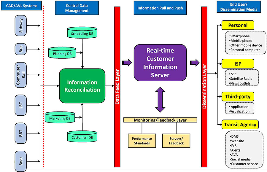
(Extended Text Description: Author’s relevant notes: Traveler Information Data Exchanges: This flowchart provides context for Traveler Information data exchanges. Generally, this diagram shows the collection of data from individual transit vehicles and data management centers, feeding data to customer information servers which process and disseminate specific traveler information to the end users. On the far left of the diagram, CAD/AVL systems that monitor the operations of each mode (in the diagram, the modes that are represented are subway, bus, commuter rail, light rail transit, bus rapid transit and boat) provide real-time information to the Information Reconciliation process, which takes input from other databases as shown: scheduling, planning, marketing and customer databases. Once all of the information is compiled and reconciled, information is sent through the Data Feed Layer to a Real-time Customer Information Server, which interfaces with the Monitoring/Feedback Layer, which interfaces with Performance Standards and Surveys/Feedback. Then, information is sent through the Dissemination Layer to various end user media, including travelers’ devices (smartphone, mobile phone, other mobile device and personal computer), information service providers (511, Satellite Radio and news outlets), third-party developers (applications and visualizations) and within the transit agency to various media (e.g., interactive voice response, dynamic message signs, website, alerts, automated voice announcements, social media and customer service).)
Slide 20:
Learning Objective #1
Example of Central System Technology Relationships
Main Point: Shows the relationships among central Traveler Information and other transit ITS technologies
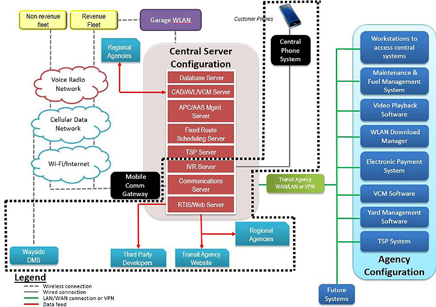
(Extended Text Description: Author’s relevant notes: Example of Central System Technology Relationships: This graphic shows the relationships among various Central System Technologies. Beginning in the center of the graphic, there is a red rectangular column representing the Central Server Configuration. In this column the following servers are represented in individual blocks from top to bottom: Database Server, CAD/AVL (Computer Aided Dispatch and Automatic Vehicle Location) Server, APC/ASA Mgmt. Server, Fixed Route Scheduling Server, TSP Server, IVR Server, Communications Server, and RTIS/Web Server. From the IVR Server, there is a gray line representing a wired connection that leads to a black box labeled "Central Phone System" with a smart phone icon above it. From the RTIS/Web Server, a red line representing data feed points down to a blue box labeled "Transit Agency Website." Coming from the left side of the RTIS/Web Server is another line pointing to blue box labeled "Third Party Developers." From the left side of the Communications Server, there is a dotted gray line that goes to a black box labeled "Comm Gateway" and branches upwards through three cloud networks (bottom to top: the Wi-Fi/Internet, Cellular Network, and Radio systems), going on to two separate yellow boxes. These boxes are labeled "Revenue Fleet" and "Non-revenue Fleet." From the Cellular network cloud, there is another dotted gray line going downwards representing the wireless connection to the Wayside DMS. Coming from the entire Central Server Configuration, there is a solid green line representing the LAN/WAN connection or VPN. This line goes through a light green box labeled "Transit Agency WAN and LAN" and branches out to a light blue section identified as the "Agency Configuration." Within the "Agency Configuration," the following items are represented in individual dark blue boxes (top to bottom): Electronic Payment System, Maintenance Management System, Video Playback Software, WLAN Download Manager, Workstations to access central systems, VCM Software, and TSP System. Outside the "Agency Configuration," the LAN/WAN connection also leads to a dark blue box labeled as "Future Systems." There is a dotted line around several components of the diagram to illustrate the traveler information-related elements. The dotted line surrounds the following diagram components: Customer Phones; Central Phone System; three components within the Central Server Configuration: IVR Server, Communications Server and RTIS/Web Server; Wayside DMS; Third Party Developers; Transit Agency Website; and Regional Agencies.)
Slide 21:
Learning Objective #1
Example of Onboard Technology Relationships
Main Point:
Shows the relationships among on-board Traveler Information and Transit Management technologies.
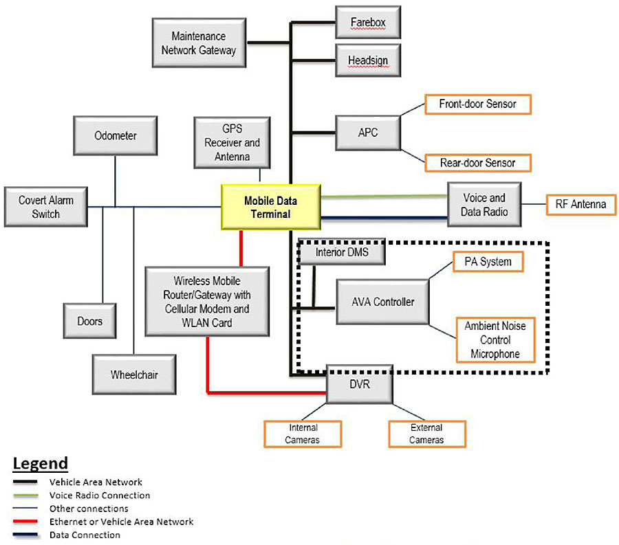
(Extended Text Description: Author’s relevant notes: Example of Onboard Technology Relationships: This graphic shows an example of the relationships among various ITS technologies onboard a vehicle. In the center of the diagram is a box labeled MDT (Mobile Data Terminal). Coming from the top of MDT, is a box labeled "GPS Receiver and Antenna" connected via a voice radio connection. Connected to the MDT via a vehicle area network are the Maintenance Network Gateway, farebox, headsign and APC. The APC is connected to the front-door sensor and rear-door sensor via an alternative link. Utilizing both a Voice Radio Connection and a Data Connection, the MDT is connected to the Voice and Data Radio. This is then connected to the RF antenna. Connected by another vehicle area network are the Interior DMS, the ASA Controller, and the DVR. The ASA controller is then connected to the PA system and Ambient Noise Control Microphone. The DVR is connected to internal and external cameras. Coming from the bottom of the MDT rectangle is a red line representing an Ethernet link. This link connects a Wireless Mobile Router/Gateway with cellular modem and WLAN card. This link continues and also connects to the DVR. To the left, the MDT is also connected to the following: Collision Avoidance, Odometer, Covert Alarm Switch, Doors, and Wheelchair. There is a dotted line around several components of the diagram to illustrate the traveler information-related elements. The dotted line surrounds the following diagram components: Interior DMS; PA system; Ambient Noise Control Microphone; and AVA Controller.)
Slide 22:
Learning Objective #1
Service Packages (SPs)
- Represent slices of physical architecture
- Collects subsystems, equipment packages, and architecture flows that provide desired service
- There are 12 traveler information-related SPs
- The most relevant SP to this module is Transit Traveler Information
Slide 23:
Learning Objective #1
Transit Traveler Information Service Package Example
Main Point: An example of one traveler information SP diagram.
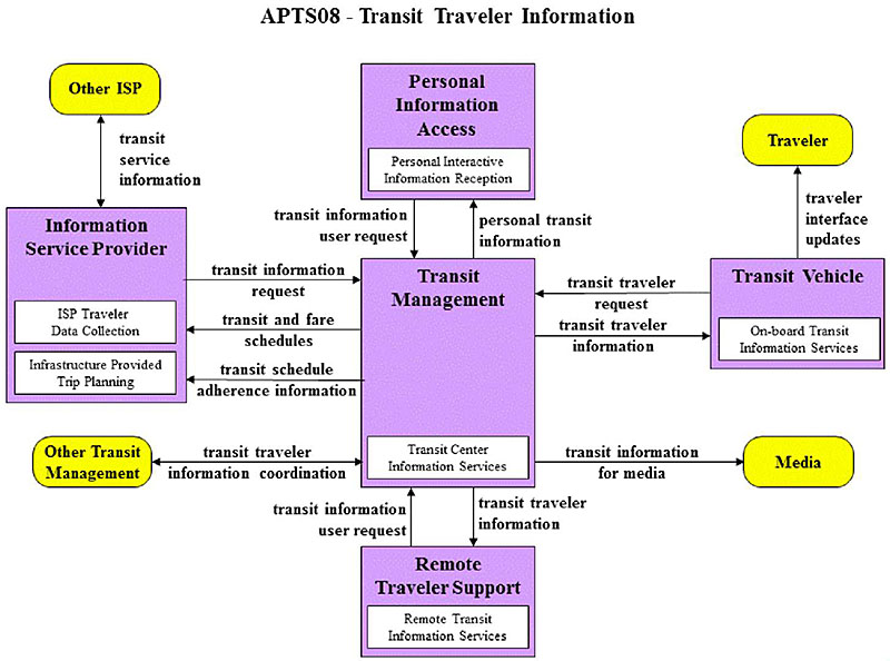
(Extended Text Description: Author’s relevant notes: Transit Traveler Information Service Package Example: This graphic has a rectangular box in the center which is labeled Transit Management and is purple in color. Within Transit Management is another smaller rectangle labeled Transit Center Vehicle Tracking and is white in color. Above the Transit Management box is a rectangle labeled Personal Information Access, which is purple in color. Within Personal Information Access is another smaller rectangle labeled Personal Interactive Information Reception and is white in color. There is a line with an arrow from Transit Management to the Personal Information Access box, which is labeled "personal transit information." There is a line with an arrow from the Personal Information Access box to Transit Management, which is labeled "transit information user request." To the right of Transit Management is a rectangle labeled Transit Vehicle, which is purple in color. Inside Transit Vehicle is another smaller rectangle labeled On-board Transit Information Services, which is white in color. Above the Transit Vehicle box is an oval labeled Traveler, which is yellow in color. There is a line with an arrow from the Transit Vehicle box to the Traveler oval, which is labeled "traveler interface updates." There is a line with an arrow from Transit Vehicle to Transit Management, which is labeled "transit traveler request." There is a line with an arrow from Transit Management to Transit Vehicle, which is labeled "transit traveler information." Below the Transit Management box is a rectangle labeled Remote Traveler Support, which is purple in color. Within Remote Traveler Support is another smaller rectangle labeled Remote Transit Information Services and is white in color. There is a line with an arrow from Transit Management to the Remote Traveler Support box, which is labeled "transit traveler information." There is a line with an arrow from the Remote Traveler Support box to Transit Management, which is labeled "transit information user request." To the right of the Transit Management box is an oval labeled Media, which is yellow in color. There is a line with an arrow from the Transit Management box to the Media oval, which is labeled "transit information for media." To the left of Transit Management is a rectangle labeled Information Service Provider, which is purple in color. Inside Information Service Provider are two other smaller rectangles labeled ISP Traveler Data Collection and Infrastructure Provided Trip Planning, which are white in color. There are two lines with arrows from Transit Management to the Information Service Provider box, which are labeled "transit and fare schedules" and "transit schedule adherence information." There is a line with an arrow from the Information Service Provider box to Transit Management, which is labeled "transit information request." Above the Information Service Provider box is an oval labeled Other ISP, which is yellow in color. There is a line with an arrow to and from Information Service Provider to Other ISP, which is labeled "transit service information." To the left of the Transit Management box is an oval labeled Other Transit Management, which is yellow in color. There is a line with an arrow to and from the Transit Management box to the Other Transit Management oval, which is labeled "transit traveler information coordination." This service package provides transit users at transit stops and on-board transit vehicles with ready access to transit information. The information services include transit stop annunciation, imminent arrival signs, and real-time transit schedule displays that are of general interest to transit users. Systems that provide custom transit trip itineraries and other tailored transit information services are also represented by this service package.)
Slide 24:
Summary of Learning Objective #1
Summarize Key Concepts from Traveler Information Standards, Part 1 of 2
- All traveler information technologies are dependent upon other technologies
- "Vee" model is the systems engineering process (SEP) that facilitates system development and deployment, including the identification and incorporation of ITS standards
- 12 Traveler Information Service Packages (SPs)
Slide 25:
Learning Objective #2: Illustrate the Structure and Use of Data Exchange Standards for Traveler Information Systems
- How to meet user needs by using standards
-
Structure of standards in addition to Transit Communications Interface Profiles (TCIP)
- For example, General Transit Feed Specification (GTFS) and TransXChange
Slide 26:
Learning Objective #2
Standards Facilitate Meeting User Needs
-
User need:
- Requirement for system to solve problem experienced by user
- Part of the systems engineering process (SEP)
- FTA National ITS Architecture Policy includes identification of applicable ITS standards
- May be satisfied by applying or adhering to standards
-
Standards being applied to meet user needs:
- Users may avoid costly customization
- Data exchanges facilitated among applications and entities
- Can choose most suitable and cost-effective applications, knowing they use common standards
Slide 27:
Learning Objective #2
Standards Facilitate Meeting User Needs (cont.)
-
Benefits from using standards:
- Reducing complexity and cost in procurement, development, and management
- Ensuring wider choice of suppliers
- Enhancing economic performance of systems due to certain types of standards
Slide 28:
Learning Objective #2
Standards Facilitate Meeting User Needs: Example
- Transit agency provides real-time data to developers for creation of mobile applications
- Data provided in standards-defined format to make it easier for developers to create application
- Automatic vehicle location (AVL) system required to generate information in General Transit Feed Specification (GTFS)-realtime format (considered de facto standard)
- AVL data could be provided in any format to meet user need, but greatly facilitated by use of GTFS-realtime format/standard
Slide 29:
Learning Objective #2
Standards Facilitate Meeting User Needs: Value
-
Protection of investment:
- Modularization and incremental deployment
- Choice of suppliers
- Reuse
Slide 30:
Learning Objective #2
Standards Facilitate Meeting User Needs: Value (cont.)
-
Interoperability:
- Roadmap for evolution
- Data management
Slide 31:
Learning Objective #2
Standards Facilitate Meeting User Needs: Value (concluded)
-
Improved quality and value:
- Risk reduction
- Better abstraction
- Better testing
- Process and tool support
- Modularization
- Reuse
Slide 32:
Learning Objective #2
Standards Facilitate Meeting User Needs: Criteria for Evaluating a Standard
-
Technical:
- How well it represents a problem
- What technologies does it use
-
Organizational:
- How mature it is
- If it is actively supported and adopted by industry
- How long it will last
Slide 33:
Learning Objective #2
Standards Facilitate Meeting User Needs: Starting Point for Identifying Standards
- National ITS Architecture divided into interface classes
-
Interface classes:
- Defined by type of system at each end of communications path: center, field (a.k.a. infrastructure), vehicle, and traveler
- Subdivided into application areas
-
Public transit management interface classes (all bi-directional) are:
- Center-to-infrastructure (C2I)
- Center-to-vehicle/traveler (C2V)
- Center-to-center (C2C)
- Example: Application area within C2I includes bi-directional communication between transit dispatch center and dynamic message signs at transit stop
Slide 34:
Learning Objective #2
Center-to-Infrastructure (C2I) Application Area Capabilities Related to Transit
- Covers interface between transit management center and specific type of infrastructure: transit signal priority (TSP) and dynamic message signs (DMS)
-
DMS:
- Provides information to travelers
- May use various technologies capable of displaying messages using any combination of characters
-
TSP:
- Provides intersection control through local traffic signal controller
- Provides interface between traffic management center and on-street master controller
- Based on analysis of transit vehicle’s conditions (e.g., schedule adherence) and traffic characteristics for a given time and type of day
- Center invokes appropriate pre-configured traffic signal control system timing plan
Slide 35:
Learning Objective #2
Center-to-Vehicle/Traveler (C2V) Application Area Capabilities Related to Transit: Vehicle
Covers interface between transit management center and transit or paratransit vehicles
- Collecting automated vehicle location information
- Collecting operational and maintenance data
- Providing transit vehicle driver with electronic dispatch and routing instructions
- Providing traveler information to vehicle
- Providing schedule information used to develop corrective actions onboard
- Providing fare management information, including invalid traveler credit identities, to transit vehicles
- Supporting transit vehicle operator authentication and ability to remotely disable vehicle in emergency situations
Slide 36:
Learning Objective #2
Center-to-Vehicle/Traveler (C2V) Application Area Capabilities Related to Transit: Traveler
Covers interfaces between traveler information providers and devices used by traveling public
- General traveler information, including traffic information, transit information (fares, real-time schedules, and transactions), incident information, event information, and parking information
- Emergency traveler information, including alerts and advisories, and evacuation information
- Traveler services information (e.g., dining, lodging, etc.)
- Trip planning, using various modes of surface transportation and route options
- Route guidance
Slide 37:
Learning Objective #2
Center-to-Center (C2C) Application Area Capabilities Related to Transit
- Multimodal coordination between transit agencies and other public transportation modes
- Transit incident information, schedules, and fare and pricing information
- Transit information suitable for media use
- Emergency transit schedule information to other operations centers
- Transit system information to traffic management centers
- Personalized transit routes requested by travelers
- Financial institution approval and status of electronic fare payments
- Law enforcement regarding the notification of violations
Slide 38:
Learning Objective #2
Identifying Appropriate Standards
- Application Areas provide a starting point for identifying appropriate ITS standards
- Use USDOT’s ITS Standards website
- Example: Transit Traveler Information, which is in the C2C Interface Class
Applicable Standards
In general, the following standards are applicable to Traveler Information deployments. To determine which specific standards are applicable for a deployment you will need to determine which architecture flows will be needed for the Traveler Information piece of your deployment. Contract your local FHWA ITS Division Specialist or an ITS Standards Program Field Support Team contact
| Standard | Development Status |
|---|---|
| NTCIP 1102 Octet Encoding Rules (OER; Base Protocol; | Published |
| NTCIP 1104 Center-to-Center Naming Convention Specification; | Published |
| NTCIP 2104 Ethernet Subnetwork Profile; | Published |
| NTCIP 2202 Internet (TCP/IP and UDP/IP) Transport Profile; | Published |
| NTCIP 2303 File Transfer Protocol (FTP) Application Profile; | Published |
| NTCIP 2304 Application Profile for DATEX-ASN (AP-DATEX); | Published |
| NTCIP 2306 Application Profile for XML Message Encoding and Transport in ITS Center-to-Center Communications (C2C XML); | Published |
| NTCIP 3003 Profile Framework; | Published |
| NTCIP 9001 NTCIP Guide; | Published |
| SAE J2266 Location Referencing Message Specification (LRMS); | Published |
| SAE J2354 Message Set for Advanced Traveler Information System (ATIS); | Published |
| SAE J2540 Messages for Handling Strings and Look-Up Tables in ATIS Standards; | Published |
| SAE J2540M RDS (Radio Data System) Phrase Lists; | Published |
| SAE J2540y2 ITIS (International Traveler Information Systems) Phrase Lists; | Published |
| SAE J2540/3 National Names Phrase List; | Published |
Slide 39:
Learning Objective #2
Structure of Standards: GTFS
-
General Transit Feed Specification (GTFS):
- Defines common format for public transportation schedules and associated geographic information
- "Feeds" allow public transit agencies to publish their transit data and developers to write applications that consume that data in an interoperable way
-
Structure: Comma-delimited text files
- Six mandatory files: agency information, stops, routes, trips, stops times, and calendar
- Seven optional files: calendar dates, fare attributes, fare rules, shapes, frequencies, transfers and feed info
- Considered "de facto" standard
- Adoption substantially outpaced TCIP and Service Interface for Real Time Information (SIRI) standards in North America
Slide 40:
Learning Objective #2
Structure of Standards: GTFS-realtime
- Feed specification that provides real-time updates about public transit fleet to application developers
-
Developed by Google as extension to GTFS and designed around:
- Ease of implementation
- GTFS interoperability
- Focus on passenger information
-
Currently supports the following types of information:
- Trip updates - delays, cancellations, changed routes
- Service alerts - stop moved, unforeseen events affecting a station, route, or entire network
- Vehicle positions - information about vehicles including location and congestion level
- Updates of each type provided in separate feed. Feeds served via HTTP and updated frequently
- Format based on protocol buffers
Slide 41:
Learning Objective #2
Structure of Standards: SIRI
- CEN/TS 15531-1: Public Transport - Part 1: Context and framework
- CEN/TS 15531-2: Public Transport - Part 2: Communications infrastructure
- CEN/TS 15531-3: Public Transport - Part 3: Functional service interfaces
- CEN/TS 15531-4: Public Transport - Part 4: Functional service interfaces: Facility Monitoring
- CEN/TS 15531-5: Public Transport - Part 5: Functional service interfaces: Situation Exchange
Slide 42:
Learning Objective #2
Structure of Standards: SIRI (cont.)
-
Uses extensible Markup Language (XML) - two layers:
- Transport (how the data is transported)
-
Payload (the domain data exchanged), wrapped in Mediation layer, which:
- Provides common management functions
- Describes policies associated with exchange behavior
-
SIRI messages exchanged as either:
- XML documents with http POST
- Simple Object Access Protocol (SOAP)
Slide 43:
Learning Objective #2
Structure of Standards: SIRI (concluded)
-
Uses consistent general communication protocols to exchange information between client and server, using following patterns:
- Request/Response allows for ad hoc exchange of data on demand from client
- Publish/Subscribe allows for repeated asynchronous push of notifications and data to distribute events and situations
- Websites: http://user47094.vs.easily.co.uk/siri/index.htm (content is no longer available) and https://www.vdv.de/siri.aspx
Slide 44:
Learning Objective #2
Structure of Standards: TransXChange
-
Two main variants:
- Registration schema: Defines XML document for registering bus services with VOSA
- General schema: Defines XML document for exchanging bus timetables and related information
-
Three components:
- TransXChange Schema: Model and formal XML schema (and variants) for describing and encoding bus schedules as XML documents
- TransXChange Documents and Process: Description and explanation of standard, including rules for creating, managing, and using TransXChange documents with software tools
- TransXChange Publisher: Free tool issued along with TransXChange, schemas which allows users to render TransXChange XML documents into readable timetable-like layout
Slide 45:
Learning Objective #2
Overview of TransXChange Use
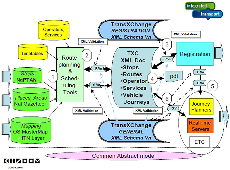
(Extended Text Description: Author’s relevant notes: Overview of TransXChange Use. The slide shows the use of TransXChange to make a registration with VOSA under the Electronic Bus Schedule Registration system. The slide shows a flowchart with the following steps: 1. Bus schedule data is prepared using scheduling software, including stop data from NaPTAN and route and geospatial data from other sources. 2. The schedule is exported as a TransXChange XML document to VOSA for registration. On export, the document is validated against a specified version of the schema. Note that TransXChange documents can also in principle be created by hand, though this would be both tedious and error prone. 3. The schedule is then imported by VOSA and Local Transport Authorities. On import, the document is validated against the version of the schema indicated by the document. 4. Following validation, the registered particulars alone are rendered as a readable pdf document using the Registration option of the TransXChange publisher. 5. The schedule is then imported by information system builders such as journey planners and AVL system implementers. 6. All or part of routes and schedules may be exchanged by system providers, annotated with additional operational data, over and above the registered particulars.)
Slide 46:
Learning Objective #2
Structure of Standards: Other Relevant Standards/Formats
- JavaScript Object Notation (JSON)
- Protocol Buffers
- Representational state transfer (REST)
- Simple Object Access Protocol (SOAP)
- eXtensible Markup Language (XML)
-
Other standards for traveler information exist in:
- International Organization for Standardization (ISO)
- Comité Européen de Normalisation (CEN) (French for European Committee for Standardization)
- UK (e.g., TransXChange)
Slide 47:
Slide 48:
Learning Objective #2
Which one of these standards is not a traveler information standard?
Answer Choices
- Service Interface for Real Time Information (SIRI)
- Society of Automotive Engineers (SAE) J1939
- TransXChange
- GTFS
Slide 49:
Learning Objective #2
Review of Answers
a) SIRI
Incorrect. SIRI is an XML protocol for exchange of public transport real-time information.
b) SAE J1939
Correct! This is an on-board Vehicle Area Network (VAN) standard.
c) TransXChange
Incorrect. TransXChange is a UK national data standard for the exchange of bus route and timetable information.
d) GTFS
Incorrect. GTFS defines a common format for public transportation schedules and associated geographic information.
Slide 50:
Summary of Learning Objective #2
Illustrate the Structure and Use of Data Exchange Standards for Transit Management Systems
- Three interface classes: C2C, C2I, and C2V
-
Other standards are in a variety of formats:
- GTFS and GTFS-realtime
- SIRI
- TransXChange
- JavaScript Object Notation (JSON)
- Protocol Buffers
- Representational State Transfer (REST)
- Simple Object Access Protocol (SOAP)
- eXtensible Markup Language (XML)
Slide 51:
Learning Objective #3: Select Appropriate ITS Standards for Data Exchange Among Traveler Information Systems, and Between Transit Management Systems and Traveler Information, and Other Systems (e.g., Traffic Management Systems)
- Life-cycle cost considerations
- Case study for selection of standards
- Case study for standards use
- Using standards to facilitate integration with legacy systems
Slide 52:
Learning Objective #3
Life-Cycle Cost Considerations
-
Standards-based products should:
- Be available from a number of suppliers at lower cost
- Have a longer lifetime providing specific advantages
-
Modularization and incremental deployment:
- Provides technical advantages
- Allows for incremental approach to adoption, meaning users spread investment over extended period
- Choice of suppliers - Systems using interfaces based on standards can be implemented as discrete pluggable modules that can be chosen from wide variety of suppliers in competitive market
- Reuse - Significantly reduce costs of specifying, procuring, and integrating system
Slide 53:
Learning Objective #3
Life-Cycle Cost Considerations (cont.)
- Development - Standards complex and expertise needed to develop and validate
- Availability - Must wait for standard to be published and confirm widespread adoption
- Maintenance - If standard changes, there can be additional costs to users
- Procurement - If standard not used, costs associated with additional technical and marketplace complexity
- Adaptation - Standard or organization may need to be adapted to meet specific requirements
- Certification - When required, formal certification of compliance may add costs
- Gold-plating - Using standards may give organization items that it does not need
Slide 54:
Learning Objective #3
Case Study for Selection of Standards: Massachusetts Bay Transportation Authority (MBTA), Boston, MA
- MBTA: 1.3 million daily riders; 75 member cities and towns; heavy rail, light rail, commuter rail, bus, trackless trolley, ferry and paratransit
-
MBTA’s open data program:
- Started in 2009
- Added real-time data in 2010
- Integrated social media
-
Rapid development of open data program:
- Underlying systems providing data independently
- Data feeds incompatible due to variety of standards and formats
-
Choice of standards based on what was:
- Needed within Application Programming Interface (API)
- Available in marketplace
Slide 55:
Learning Objective #3
Case Study for Selection of Standards: MBTA (cont.)
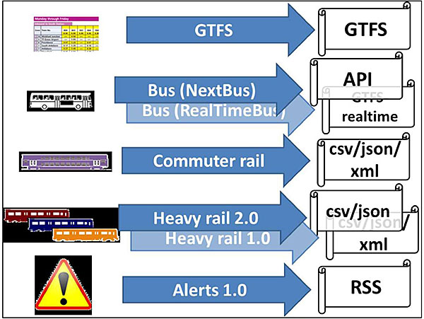
(Extended Text Description: Case Study for Selection of Standards: MBTA (cont.). This slide shows the number of standards being used for each data feed prior to the MBTA reorganizing the feeds (discussed in a future slide). The top portion of the slide shows a box with a transit schedule in it, a line labeled GTFS with an arrow to the right connected to a box to the right labeled GTFS. The next line down shows a box with a bus in it, two lines, one labeled Bus (NextBus) and the other labeled Bus (RealTimeBus), each with an arrow to the right connected to boxes to the right, one labeled API and the other labeled GTFS-realtime, respectively. The next line down shows a box with a commuter rail schedule in it, a line labeled Commuter Rail with an arrow to the right connected to a box to the right labeled "csv/json/xml." The next line down shows a box with red, blue and orange subway cars in it, two lines, one labeled Heavy Rail 2.0 and the other labeled Heavy Rail 1.0, each with an arrow to the right connected to boxes to the right, one labeled "csv/json" and the other labeled "csv/json/xml", respectively. The bottom line shows a box with a danger triangle in it, a line labeled Alerts 1.0 with an arrow to the right connected to a box to the right labeled RSS.)
Slide 56:
Learning Objective #3
Case Study for Selection of Standards: MBTA (cont.)
- Staff wanted to support GTFS-realtime and be on Google Maps
- Found SIRI verbose and somewhat complicated, so not selected
- TCIP well-suited for communications within agency, but not for communications with developers, so not selected
-
Developed API to:
- Retrieve smaller sets of information than what contained in GTFS-realtime (GTFS-RT)
- Include some information not in GTFS-RT
- Selected XML format for its API because it is industry standard for APIs
Slide 57:
Learning Objective #3
Case Study for Selection of Standards: MBTA (cont.)
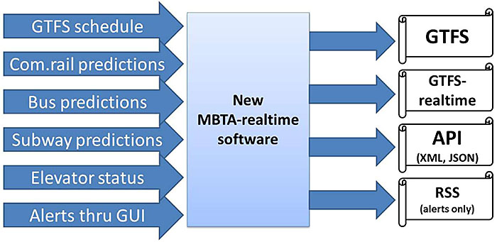
(Extended Text Description: Case Study for Selection of Standards: MBTA (cont.). This slide shows that the reorganization of the open data program and use of standards. There are six lines with arrows to the right that all connect to a box labeled New MBTA-realtime software. The six lines are labeled GTFS schedule, Com.rail predictions, Bus predictions, Subway predictions, Elevator status and Alerts thru GUIs. Then four lines with arrows to the right connect to four boxes. The top box is labeled GTFS, the next box down is labeled GTFS-realtime, the next box down is labeled API (XML, JSON) and the bottom box is labeled RSS (alerts only).)
Slide 58:
Learning Objective #3
Case Study for Selection of Standards: MBTA (concluded)
-
Re-organized feeds by developing new MBTA-realtime software:
- C# application with Microsoft SQL Server back-end on two Amazon cloud servers
- Based around foundation of GTFS data
- Feeds, MBTA website, subscription service
- Email and SMS sent by GovDelivery
- Phase 1 launched 2013, Phase 2 launched Spring 2014
- GTFS, GTFS-realtime and their API popular with developers
- No requests for TCIP or SIRI from developers to date
Slide 59:

Slide 60:
Learning Objective #3
Which standard is not being used by the MBTA for their open data program?
Answer Choices
- General Transit Feed Specification (GTFS)
- extensible Markup Language (XML)
- JavaScript Object Notation (JSON)
- Service Interface for Real Time Information (SIRI)
Slide 61:
Learning Objective #3
Review of Answers
a) GTFS
Incorrect. GTFS is one of the standards used by the MBTA.
b) XML
Incorrect. The MBTA selected XML format for its API.
c) JSON
Incorrect. JSON is also used in the MBTA API.
d) SIRI
Correct. The MBTA determined that SIRI was somewhat complicated, so they chose not to use it.
Slide 62:
Learning Objective #3
Case Study for Changing Traveler Information Standards: Metropolitan Transportation Authority (MTA), New York, NY
-
Metropolitan Transportation Authority (MTA) in New York City:
- Provides free real-time developer APIs to MTA Bus Time system
- Identified and use SIRI standard
- Represented first public-facing and free to access SIRI implementation
- SIRI did not cover "distance away" but MTA added it
- SIRI requests are typically SOAP requests sent via HTTP POST, but MTA implemented RESTful interface using HTTP GET requests
-
SIRI web service calls implemented:
- VehicleMonitoring
- StopMonitoring
Slide 63:
Learning Objective #3
Case Study for Changing Traveler Information Standards: MTA (cont.)
- MTA Bus Time provides both XML and JSON versions of API
- Two SIRI calls use MTA’s GTFS data as a reference
- OneBusAway software powering MTA Bus Time comes with free utility to strip down GTFS file to only data relevant to given route
- Committee managing SIRI adopted changes/extension MTA made
- MTA Bus Time exposes modified version of OneBusAway RESTful API
- OneBusAway is open source platform for real-time transit information
Slide 64:
Learning Objective #3
Open Source Software Criteria
- Free redistribution
- Program must include source code
- Allow modifications and derived works
- Permit distribution of software built from modified source code
- No discrimination against persons or groups
- Rights must apply to all to whom the program is redistributed without the need for execution of an additional license by those parties
- License must not be specific to a product
- License must not restrict other software
- License must be technology-neutral
Slide 65:
Learning Objective #3
Using Standards to Facilitate Integration with Legacy Systems: Portland TriMet Case Study
- TriMet: 888 vehicles operating in max service/ approx. 461 million annual passenger miles
- Use ITS standards when developing systems to maximize vendor flexibility, and data exchange compatibility
-
Functional integration example:
- No Transmission Control Protocol/Internet Protocol (TCP/IP) standards for LED sign interface at time of DMS procurement
- Forced to consider sign vendors that had proprietary protocols
- TriMet required sign vendors to interface with TCP/IP protocols
- Advantage to using TCP/IP and standard protocols that would enable use of different communication methods, yet retain same applications
Slide 66:
Learning Objective #3
Using Standards to Facilitate Integration with Legacy Systems: Portland TriMet Case Study
- New traveler information systems should be designed to support integration of data from existing legacy systems
- New real-time bus arrival estimation system built upon same platform as TriMet’s existing AVL bus dispatch and rail central control systems
- Saved software development time and system costs
- Few minor changes needed to meet different requirements necessary for reporting information to passengers (versus dispatchers)
Slide 67:
Summary of Learning Objective #3
Select Appropriate ITS Standards for Data Exchange Among Transit Management Systems and Between Other Systems
-
Six main areas of life-cycle cost considerations:
- Development
- Availability
- Maintenance
- Procurement
- Adaptation
- Gold-plating
- MBTA, MTA and TriMet examples
-
Issues associated with integration with legacy systems:
- Comply with standards and select proven commercial off-the-shelf technology
- Plan on adequate development time and thorough system testing
Slide 68:
Learning Objective #4: Illustrate How to Apply Standards to the Development of Procurement Specifications
- Read a standard
- Rigidity, flexibility and change in the application of standards
- Incorporate a standard into a specification for procuring a Traveler Information system
- Test and determine conformance with a standard
- Standards and intellectual property
Slide 69:
Learning Objective #4
Read a Standard
-
Traveler information standards not structured the same way:
- GTFS is a series of comma-delimited text files
- GTFS-realtime format based on protocol buffers
- SIRI is in XML format
- TransXChange is in XML format
-
Need to understand enough to:
- Identify appropriate standard(s) based on aforementioned criteria
- Define use of standard(s) in functional requirements/specifications
- Define how compliance with standard(s) can be tested
Slide 70:
Learning Objective #4
Read a Standard: GTFS
| Filename | Required | Defines |
|---|---|---|
| agency.txt | Required | One or more transit agencies that provide the data in this feed. |
| stops.txt | Required | Individual locations where vehicles pick up or drop off passengers. |
| routes.txt | Required | Transit routes. A route is a group of trips that are displayed to riders as a single service. |
| trips.txt | Required | Trips for each route. A trip is a sequence of two or more stops that occurs at specific time. |
| stop_times.txt | Required | Times that a vehicle arrives at and departs from individual stops for each trip. |
| calendar.txt | Required | Dates for service IDs using a weekly schedule. Specify when service starts and ends, as well as days of the week where service is available. |
| calendar_dates.txt | Optional | Exceptions for the service IDs defined in the calendar.txt file. If calendar_dates.txt includes ALL dates of service, this file may be specified instead of calendar.txt. |
| fare_attributes.txt | Optional | Fare information for a transit organization’s routes. |
| fare_rules.txt | Optional | Rules for applying fare information for a transit organization’s routes. |
| shapes.txt | Optional | Rules for drawing lines on a map to represent a transit organization’s routes. |
| frequencies.txt | Optional | Headway (time between trips) for routes with variable frequency of service. |
| transfers.txt | Optional | Rules for making connections at transfer points between routes. |
| feed_info.txt | Optional | Additional information about the feed itself, including publisher, version, and expiration information. |
Slide 71:
Learning Objective #4
Read a Standard: GTFS (cont.)
agency.txt
agency_id, agency_name,agency_url,agency_timezone,agency_phone,agency_lang
FunBus,The Fun Bus,http://www.thefunbus.org,America/Los_Angeles,(310) 555-0222,en
stops.txt
stop_id,stop_name,stop_desc,stop_lat,stop_lon,stop_url,location_type,parent_station
S1,Mission St. & Silver Ave.,The stop is located at the southwest corner of the intersection.,37.728631,-122.431282,,,
S2,Mission St. & Cortland Ave.,The stop is located 20 feet south of Mission St.,37.74103,-122.422482,,,
S3,Mission St. & 24th St.,The stop is located at the southwest corner of the intersection.,37.75223,-122.418581,,,
S4,Mission St. & 21st St.,The stop is located at the northwest corner of the intersection.,37.75713,-122.418982,,,
S5,Mission St. & 18th St.,The stop is located 25 feet west of 18th St.,37.761829,-122.419382,,,
S6,Mission St. & 15th St.,The stop is located 10 feet north of Mission St.,37.766629,-122.419782,,,
S7,24th St. Mission Station,,37.752240,-122.418450,,,S8
S8,24th St. Mission Station,,37.752240,-122.418450,http://www.bart.gov/stations/stationguide/stationoverview_24st.asp,1,
routes.txt
route_id,route_short_name,route_long_name,route_desc,route_type
A,17,Mission,"The ""A"" route travels from lower Mission to Downtown.",3
Slide 72:
Learning Objective #4
GTFS-realtime
- GTFS-realtime format based on protocol buffers, language- and platform-neutral mechanism for serializing structured data
- Data structure defined in GTFS-realtime.proto file, used to generate source code to read and write structured data from and to variety of data streams using variety of languages
- Hierarchy of elements and their type definitions specified in GTFS-realtime.proto file, used to generate necessary libraries in choice of programming language
- https://developers.google.com/transit/gtfs-realtime/
Slide 73:
Learning Objective #4
SIRI
-
General communications architecture, supporting two patterns of interchange:
- Synchronous request/response protocol
- Asynchronous subscribe/publish protocol
- Specific services operating within that architecture
- Primary content of messages consist of XML document
-
Two different patterns of message exchange:
- Direct delivery protocol
- Fetched delivery protocol
- Identify appropriate standard(s) based on aforementioned criteria
Slide 74:
Learning Objective #4
SIRI: Example of StopMonitoringRequest
-
Request consists of:
- Standard header (similar for all SIRI requests)
- Topics and Policies specific to SIRI-SM functional service
- Request asks for departures for stop "HLTST011"
- Response contains up to seven vehicle journeys at stop, as set by policy. If there are more than seven available, then only the first two for each line will be shown
Slide 75:
Learning Objective #4
SIRI: Example of StopMonitoringRequest (cont)
<ServiceRequest>
<RequestorRef>NADER</RequestorRef>
<RequestTimestamp>2004-12-17T09:30:47-05:00</RequestTimestamp>
<StopMonitoringRequest version="1.0">
<!-- All LlNE77services from stop EH00001to destination PLACE457 in the next 30 minutes-:
<RequestTimestamp>2004-12-17T09:30: 47-05:00</RequestTimestamp>
<MessageIdentifier>NDR06756</MessageIdentifier>
<!--=======TOPIC =============================== -->
<PreviewInterval> P30M </PreviewInterval>
<MonitoringRef> HLTST011 </MonibringRef>
<!--=======POLICY======================-->
<MaximumStopVisits>7</MaximumStopVisits >
<MinimumStopVisitsPerLine>2 </MinimumStopVisitsPerLine>
<StopMonitoringDetailLevel>normal</StopMonitoringDetailLevel>
</StopMonitoringRequest>
</ServiceRequest>
(Additional Author’s Notes for this slide: Example of StopMonitoringRequest (cont.). This slide shows an example of a StopMonitoringRequest. The request, written in XML format, consists of a standard header, which is similar for all SIRI requests, and then Topics and Policies that are specific to the SIRI-SM functional service. The request asks for the departures for a stop HLTST011. The response is to contain up to seven vehicle journeys at the stop, as set by the policy. If there are more than seven available, then only the first two for each line will be shown.)
Slide 76:
Learning Objective #4
TransXChange
-
TransXChange major components:
- XML schema
- Publisher
- Schema documentation
- Examples of schedules
-
TransXChange XML schemas:
- Registration - registering bus timetable
- General - exchanging bus timetable and ancillary data
Slide 77:
Learning Objective #4
TransXChange Schemas
- Modularized into functional packages
- Share common set of base modules with National Public Transport Access Nodes (NaPTAN)
-
Used to exchange:
- Bus schedules
- Days of service
- School holidays
- Service registration
- Bus operator information
- Operational information
- Accessibility information
Slide 78:
Learning Objective #4
TransXChange Model
- Service brings together information about registered bus service, and may contain two types of component service: Standard or Flexible
- StandardService describes normal bus schedule. Route describes physical path taken by buses as set of route links
- FlexibleService describes bus service that does not have fixed route, but only catchment area or variable stops with no prescribed pattern of use
-
StandardService has one or more JourneyPattern elements to describe logical path of traversal of stops of Route as:
- Sequence of timing links
- One or more VehicleJourney elements
Slide 79:
Learning Objective #4
TransXChange Model (cont.)
- Both types of service have registered Operator, who runs the service
- Route, JourneyPattern and VehicleJourney follow sequence of NaPTAN StopPoints
- StopPoints used in JourneyPattern or Route are either declared locally or by referenced to an external definition using an AnnotatedStopRef
- Registration specifies registration details for service. It is mandatory in registration schema.
Slide 80:
Learning Objective #4
TransXChange Model (cont.)
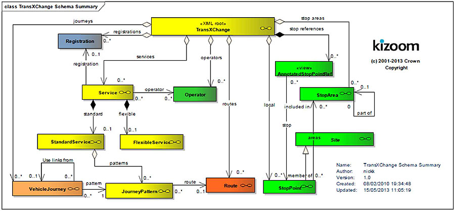
(Extended Text Description: Author’s relevant notes: TransXChange Model (cont.). This diagram shows, in UML class diagram notation, the core elements of the TransXChange schema. Reusable elements with a global scope are organized beneath the root TransXChange. There is a yellow box labeled "<XML root> TransXChange" that is connected to boxes that each represent elements of the TransXChange model. To the left of the yellow box connected by a line (labeled Registrations) with an arrow is a blue box labeled "Registration." There is another yellow box labeled "Service" that is connected by a line (labeled Registration) with an arrow to the Registration box. The "<XML root> TransXChange" box is connected by a line (labeled services) with an arrow to the "Service" box. Below the "<XML root> TransXChange" box connected by a line (labeled operators) with an arrow to a green box labeled "Operator." The "Service" box is connected by a line (labeled operator) with an arrow to the "Operator" box. The "Service" box is connected by lines (one labeled standard and the other labeled flexible) with arrows to two yellow boxes – one is labeled "StandardService" and the other is labeled "FlexibleService." The StandardService box is connected by a line (labeled patterns) with an arrow to a yellow box labeled "JourneyPattern." The box labeled "<XML root> TransXChange" is connected by a line (labeled journeys) with the arrow to an orange box labeled "VehicleJourney." The VehicleJourney box is connect by a line (labeled pattern) with an arrow to the JourneyPattern box. The JourneyPattern box is connected by a line (labeled route) with an arrow to a red box labeled "Route." The "<XML root> TransXChange" box is connected by a line (labeled routes) with an arrow to the Route box. The "<XML root> TransXChange" box is connected by a line (labeled stop references) with an arrow to a green box labeled "<view> AnnotatedStopPointRef." The "<XML root> TransXChange" box is connected by a line (labeled stop areas) with an arrow to a green box labeled "StopArea." The "<XML root> TransXChange" box is connected by a line (labeled local) with an arrow to a green box labeled "StopPoint." The "<view> AnnotatedStopPointRef" box is connected by a line (labeled stop) with an arrow to a green box labeled "StopPoint." The "StopPoint" box is connected by a line with an arrow to a green box labeled "Site." The "StopPoint" box is connected by a line (labeled areas) with an arrow to a green box labeled "Stop Area." )
Slide 81:
Learning Objective #4
Rigidity, Flexibility, and Change in the Application of Standards
- Standards are not perfect
-
Extending standards are acceptable but:
- Must be well-documented
- Follow prescribed procedures
- Vendors may claim "conformance to standards" but may not provide all features and value ranges allowed
- Beware of "cherry picking" from manufacturers datasheets
- Stick to functions needed to meet Concept of Operations (ConOps)
Slide 82:
Learning Objective #4
Rigidity, Flexibility and Change in the Application of Standards (cont.)
-
Avoid specifying proprietary features and objects:
- Both will result in non-standard, non-interoperable solutions
- If you must have a new or different "feature," document thoroughly for all to use
Slide 83:
Learning Objective #4
Incorporate a Standard into a Specification for Procuring a Traveler Information System
- Discussion of Concept of Operations (ConOps)
- Components/devices you expect to be supplied in system
- Functions to be supported, value ranges and optional capabilities required
- Detailed listing of requirements
- Language requiring use of standardized dialogs
- Testing program
Slide 84:
Learning Objective #4
Incorporate a Standard into a Specification for Procuring a Traveler Information System
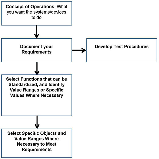
(Extended Text Description: Incorporate a Standard into a Specification for Procuring a Transit Management System: This flowchart indicates the progressive application of the standards. The first box is labeled "Concept of Operations: What you want the systems/devices to do." An arrow points downward toward the next box, which is labeled "Document your Requirements." An arrow points to the right toward the next box, which is labeled "Develop Test Procedures." The box labeled "Document your Requirements" is connected to a box below it with a down-pointing arrow. This box below is labeled "Select Functions that can be Standardized, and Identify Value Ranges or Specific Values Where Necessary." An arrow points downward to the next box, which is labeled "Select Specific Objects and Value Ranges Where Necessary to Meet Requirements.")
Slide 85:
Learning Objective #4
Structure of Standards: Excerpts from Functional Specification Using GTFS
-
Real Time Information System (RTIS)
-
General Transit Feed Specifications Export (GTFS Feed) for Google Transit Trip Planner:
- The system shall provide an interface to Google Transit using the GTFS. The interface shall allow for the export and delivery of data fields necessary (per the agency’s needs) for fixed-route trip planning on Google1. The contractor shall work with the agency...
-
The contractor shall perform or help the agency with the following processes required to deliver its fixed-route data to Google Transit:
- Shall prepare transit data as a zip file in GTFS format.
- Shall test the GTFS zip file using FieldValidator and ScheduleViewer tools...; and
- Shall review and perform a quality assurance check of Google’s preview data (beta website)...
-
General Transit Feed Specifications Export (GTFS Feed) for Google Transit Trip Planner:
1 GTFS guidelines for transit feeds are available at: http://code.google.com/transit/spec/transit feed specification.html- content is no longer available.
Slide 86:
Learning Objective #4
Test and Determine Conformance with a Standard
- Conformance: testing to determine if implementation meets requirements of standard or specification
-
Testing for:
- Performance
- Robustness
- Behavior
- Functions
- Interoperability
- Conformance testing is different - requirements or criteria for conformance must be specified in standard/specification
- If criteria or requirements for conformance not specified, there can be no conformance testing
Slide 87:
Learning Objective #4
Test and Determine Conformance with a Standard (cont.)
- Prove that implementation is correct, consistent, and complete with respect to specification
-
Alternative is falsification testing, which:
- Subjects implementation to combinations of legal and illegal inputs
-
Compares resulting output to set of corresponding "expected results"
- If errors found, implementation does not conform to specification
- If no errors, does not necessarily imply converse
- Can only demonstrate non-conformance
- The larger and more varied the inputs, the more confidence can be placed when testing generates no errors
Slide 88:
Learning Objective #4
Test and Determine Conformance with a Standard: Conformance Clause
- High-level description of what is required of implementers and application developers
-
May specify:
- Sets of functions
- Minimal requirements for certain functions and implementation-dependent values
- Permissibility of extensions, options and alternative approaches and how they are to be handled
Slide 89:
Learning Objective #4
Test and Determine Conformance with a Standard: Conformance Testing
- Ensure that "standard-based" products are implemented
-
Conformance involves two major components:
- Test tool/suite
-
Testing program (e.g., certification or branding) for those specifications/standards for:
- Critical applications
- Interoperability with other applications
- Security of systems
- Decision to establish program based on risk of nonconformance versus costs of creating and running program
Slide 90:
Learning Objective #4
Test and Determine Conformance with a Standard: Conformance Testing (cont.)
-
Conformance testing program usually includes:
- Standard or specification
- Test tool (e.g., tool, suite) and/or reference implementation
- Procedures for testing
- Organization(s) to do testing, issue certificates of validation, and arbitrate disputes
Slide 91:

Slide 92:
Learning Objective #4
Which of the following elements are included in a conformance testing program?
Answer Choices
- Standard or specification
- Procedures for testing
- Organization(s) to test/issue certificates of validation
- All of the above
Slide 93:
Learning Objective #4
Review of Answers
a) Standard or specification
This is included in a conformance testing program.
b) Procedures for testing
This is included in a conformance testing program.
c) Organization(s) to test/issue certificates of validation
This is included in a conformance testing program.
d) All of the above
Correct! All three are part of a conformance testing program.
Slide 94:
Learning Objective #4
Standards and Intellectual Property
- Best technology for technical standard could be proprietary technology, protected by one or more patents
- Standards development more frequently anticipates technology rather than following it
- Leads to conflicts between standards and patents
- If patented technology is incorporated into standard without patent holder’s agreement to share its patent rights, then patent holder may be the only entity able to comply with the standard
Slide 95:
Learning Objective #4
Standards and Intellectual Property (cont.)
- Agency should verify if "essential" patent for which license is required, and broad terms and conditions under which license will be granted
- Information generally available from relevant Standards Development Organization (SDO)
-
If license obtained directly from patent holder:
- Patent holder should be contacted
- Licensing agreement negotiated and signed prior to adopting standard
- Agency may have option of choosing from alternative technologies to comply with a given standard
- May include use of protected or patented technology
Slide 96:
Learning Objective #4
Standards and Intellectual Property (concluded)
- In all such cases, patents would not be considered to be "essential patents" but "useful patents"
- Essential patents may be pooled by patent holders
-
Compliance with given standard or technical regulation may require using one or more patented technologies. In all such cases:
- Required to obtain license from patent holder
- Must be done prior to using patented technology to conform to requirements of standard
- Know rules so you are able to negotiate best possible terms and conditions for use of proprietary or patented technology
Slide 97:
Summary of Learning Objective #4
Illustrate How to Apply Standards to the Development of
Procurement Specifications
- Different standards have different structures
-
Standards not static and can change. Standard extensions can be used, but:
- Must be well-documented
- Follow prescribed procedures
- Five components to incorporate standard into procurement
-
Conformance testing program includes:
- Standard or specification
- Test tool
- Procedures for testing
- Organization(s) to do testing, issue certificates of validation, and arbitrate disputes
- Agency that plans to adopt standard should verify if any "essential" patent(s) for which a license is required
Slide 98:
What We Have Learned
- Service packages represent slices of the physical architecture that address specific services like surface street control.
-
The use of standards is desirable for both business and technical reasons. The principal benefits of standards are as follows:
- protection of investment
- interoperability
- improved quality and value
- Application areas provide a starting point for identifying the ITS standards and other resources, and are deployment-oriented categories that focus on commonly deployed ITS services or systems.
- Using standards in a deployment can greatly reduce component development costs, especially if standardized off-the-shelf components are available.
- The requirements or criteria for conformance must be specified in the standard or specification.
Slide 99:
Resources
- ITS ePrimer: Module 7: Public Transportation, eprimer/documents/module7p.pdf
- Transit Traveler Information Service Package, http://www.iteris.com/itsarch/html/mp/mpapts08.htm- content is no longer available.
- Transport Direct, "Guide on the use of standards for travel information and retailing," https://www.gov.uk/government/uploads/system/uploads/attachment data/file/4360/standards-guide.pdf
- ITS Standards Program, About ITS Standards: Application Areas, http://www.standards.its.dot.gov/LearnAboutStandards/ApplicationAreas
- General Transit Feed Specification (GTFS): https://developers.google.com/transit/gtfs/
- General Transit Feed Specification (GTFS)-realtime: https://developers.google.com/transit/gtfs-realtime/
- Service Interface for Real Time Information (SIRI), CEN/TS 15531 (prCEN/TS-OO278181), http://user47094.vs.easily.co.uk/siri/-content is no longer available
- Gov.UK, "TransXChange," https://www.gov.uk/government/collections/transxchange
Slide 100:
Next Course Modules
Students who have completed Module 7 may delve into the following PCB modules:
- Module 8: Arterial Management & Transit Signal Priority, Part 1 of 2
- Module 9: Arterial Management & Transit Signal Priority, Part 2 of 2
- Module 10: Electronic Fare Payment Systems
- Module 11: Transit and Connected Vehicle Environment / Emerging Technologies, Applications, and Future Platforms
Slide 101:
Thank you for completing this module.