ITS Transit Standards Professional Capacity Building Program
Module 8: Arterial Management and Transit Signal Priority: Understanding User Needs for Signal Control Priority (SCP) Based on NTCIP 1211 Standard, Part 1 of 2
HTML of the PowerPoint Presentation
(Note: This document has been converted from a PowerPoint presentation to 508-compliant HTML. The formatting has been adjusted for 508 compliance, but all the original text content is included, plus additional text descriptions for the images, photos and/or diagrams have been provided below.)
Slide 1:
(Extended Text Description: Welcome - Graphic image of introductory slide. A large dark blue rectangle with a wide, light grid pattern at the top half and bands of dark and lighter blue bands below. There is a white square ITS logo box with words "Standards ITS Training" in green and blue on the middle left side. The word "Welcome" in white is to the right of the logo. Under the logo box is the logo for the U.S. Department of Transportation, Office of the Assistant Secretary for Research and Technology.)
Slide 2:
(Extended Text Description: This slide, entitled "Welcome" has a photo of Ken Leonard, Director, ITS Joint Program Office, on the left hand side, with his email address, Ken.Leonard@dot.gov. A screen capture snapshot of the home webpage is found on the right hand side - for illustration only - from August 2014. Below this image is a link to the current website: www.its.dot.gov/pcb - this screen capture snapshot shows an example from the Office of the Assistant Secretary for Research and Development - Intelligent Transportation Systems Joint Program Office - ITS Professional Capacity Building Program/Advanced ITS Education. Below the main site banner, it shows the main navigation menu with the following items: About, ITS Training, Knowledge Exchange, Technology Transfer, ITS in Academics, and Media Library. Below the main navigation menu, the page shows various content of the website, including a graphic image of professionals seated in a room during a training program. A text overlay has the text Welcome to ITS Professional Capacity Building. Additional content on the page includes a box entitled What’s New and a section labeled Free Training. Again, this image serves for illustration only. The current website link is: https://www.its.dot.gov/pcb.)
Slide 3:
ITS Transit Standards Professional Capacity Building Program
Module 8:
Arterial Management and Transit Signal Priority: Understanding User Needs for Signal Control Priority (SCP) Based on NTCIP 1211 Standard, Part 1 of 2
Patrick Chan
Slide 4:

Slide 5:
Instructor
Patrick Chan, P.E.
Senior Technical Staff
Consensus Systems Technologies
Flushing, NY, USA
Slide 6:
Target Audience
- Transit managers;
- Transit planning, operations, and maintenance staff;
- Traffic management operations staff;
- Transit and Traffic systems acquisitions staff;
- Transit electronic maintenance staff;
- Integrated Corridor Management project and operations team;
- Transit technology vendors; and
- Transit ITS contractors and consultants.
Slide 7:
Recommended Prerequisite(s)
| Decision-Maker | Project Manager | Project Engineer | |
|---|---|---|---|
| Module 1: Introduction to ITS Transit Standards | ✓ | ✓ | ✓ |
| Module 2: Transit Management Standards, Part 1 of 2 | ✓ | ✓ | ✓ |
| Module 3: Transit Communications Interface Profiles (TCIP), Part 1 of 2 | ✓ | ✓ | ✓ |
| Module 4: Transit Communications Interface Profiles (TCIP), Part 2 of 2 | N/A | ✓ | ✓ |
| Module 5: Transit Management Standards, Part 2 of 2 | N/A | ✓ | ✓ |
Slide 8:
Curriculum Path (Project Manager)
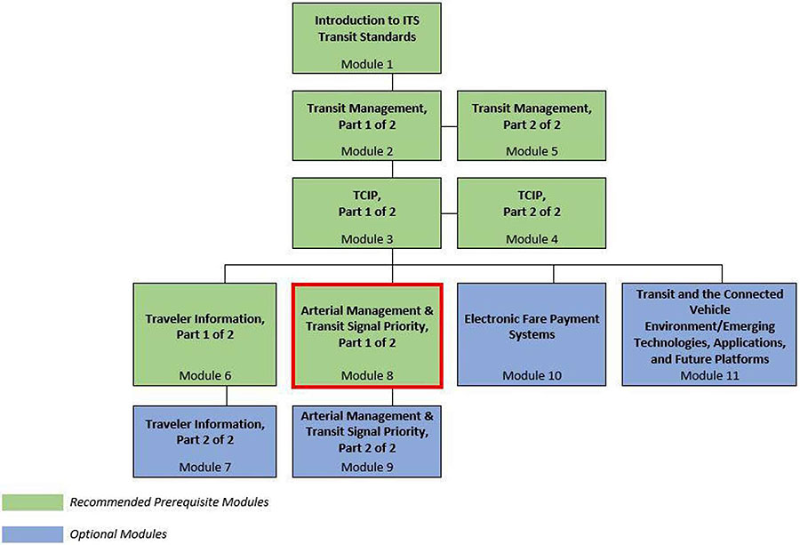
(Extended Text Description: Curriculum Path for Project Manager. A graphical illustration indicating the sequence of training modules and where this module fits in. Each module is represented by a box with the name of the module in it and a flow chart showing the logical flow of the modules with the current module boxed in red. The first three horizontally sequenced boxes are green. The first box is "Introduction to ITS Transit Standards, Module 1." Below that, connected by a line, is a box with the text "Transit Management, Part 1 of 2." To the right of this box, is "Transit Management, Part 2 of 2". Below that "Transit Management, Part 1 of 2", connected by a line, is a box with the text, "TCIP, Part 1 of 2." To the right of this box, is "TCIP, Part 2 of 2." From here, the lines branch out into four text boxes that are horizontally sequenced. The first two: "Traveler Information, Part 1 of 2" and "Arterial Management & Transit Signal Priority, Part 1 of 2" which is outlined in red, are green. The last two are "Electronic Fare Payment Systems" and "Transit and the Connected Vehicle Environment/Emerging Technologies, Applications, and Future Platforms." Below "Traveler Information, Part 1 of 2," is the text box "Traveler Information, Part 2 of 2" coded in blue. Below "Arterial Management & Transit Signal Priority, Part 1 of 2", is the text box "Arterial Management & Transit Signal Priority, Part 2 of 2," coded in blue.)
Slide 9:
Curriculum Path (Project Engineer)
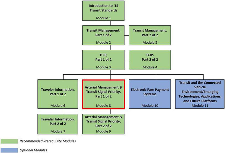
(Extended Text Description: Curriculum Path for Project Engineer. A graphical illustration indicating the sequence of training modules and where this module fits in. Each module is represented by a box with the name of the module in it and a flow chart showing the logical flow of the modules with the current module boxed in red. The first three horizontally sequenced boxes are green. The first box is "Introduction to ITS Transit Standards, Module 1." Below that, connected by a line, is a box with the text "Transit Management, Part 1 of 2." To the right of this box, is "Transit Management, Part 2 of 2". Below that "Transit Management, Part 1 of 2", connected by a line, is a box with the text, "TCIP, Part 1 of 2." To the right of this box, is "TCIP, Part 2 of 2." From here, the lines branch out into four text boxes that are horizontally sequenced. The first two: "Traveler Information, Part 1 of 2" and "Arterial Management & Transit Signal Priority, Part 1 of 2" which is outlined in red, are green; the last two are "Electronic Fare Payment Systems" and "Transit and the Connected Vehicle Environment/Emerging Technologies, Applications, and Future Platforms." Below "Traveler Information, Part 1 of 2," is the text box "Traveler Information, Part 2 of 2" coded in green. Below "Arterial Management & Transit Signal Priority, Part 1 of 2", is the text box "Arterial Management & Transit Signal Priority, Part 2 of 2," coded in green.)
Slide 10
Learning Objectives
- Identify the needs addressed by and the benefits of Signal Control Priority (SCP) on an arterial
- Identify the components that form an SCP System
- Describe the different SCP system architectures and the considerations in selecting an architecture for implementation
- Identify the interfaces in an SCP System and the ITS standards that addresses each of these interfaces
- Identify the user needs addressed by the standards
- Describe at a high level how to incorporate ITS standards into an SCP system procurement
- Describe other arterial management tools and strategies
Slide 11:
Learning Objective #1: Identify the Needs Addressed by and the Benefits of Signal Control Priority (SCP) on an Arterial
- Describe the purpose of an SCP System
- Describe how an SCP may improve transit operations
Slide 12:
Learning Objective #1
Describe the Purpose of an SCP System
Typical Scenario
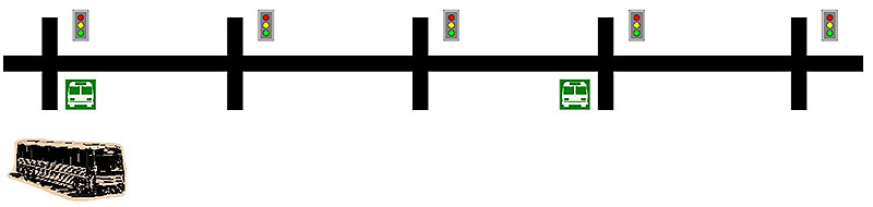
(Extended Text Description: A graphical illustration depicting an arterial street with five intersections. Each intersection has a traffic signal to control traffic. Two of the intersections have transit stops, which are depicted by a transit bus icon. The first transit stop is downstream of the intersection (after the intersection) and the second transit stop is upstream of the intersection (before the intersection). A graphic of a transit bus is also depicted at the beginning of the arterial street, to indicate this is a transit route.)
Slide 13:
Learning Objective #1
Describe the Purpose of an SCP System
Transit Challenges
What does a transit manager need:
- Reduce unreliable travel times and/or poor schedule adherence due to recurring or non-recurring congestion
- Reduce slow travel times on arterials due to recurring or non-recurring congestion
- Reduce delay or unreliability due to traffic signals
- Reduce high energy usage by fleet vehicles due to congestion or intersection queues

Slide 14:
Learning Objective #1
Describe the Purpose of an SCP System Signal Control Priority (SCP)
- An operational strategy that provides preferential treatment (priority) to facilitate the movement of fleet vehicles through signalized intersections
An SCP system improves transportation system operations by:
- Providing preferential treatment for certain pre-identified vehicles at signalized intersections without degrading the overall performance of the traffic network
- Providing more efficient use of the street network by improving the throughput of travelers and goods
- Improving on-time performance and schedule adherence of public transportation
Slide 15:
Learning Objective #1
Describe the Purpose of an SCP System (cont.)
Signal Control Priority (SCP)
How can traffic signal engineers provide priority?
-
Provide a green phase earlier
- Clear queues ahead of the fleet vehicle
- Allow the fleet vehicle to move earlier
- Extend the green phase
-
Activate a special phase for the vehicle
- Queue jump
- Protected turn
Slide 16:
Learning Objective #1
Describe How an SCP may Improve Transit Operations
Transit Signal Priority (TSP)
- A subset of Signal Control Priority (SCP) focusing on transit fleet vehicles.
The benefits of an SCP System for transit service includes:
-
Increased attractiveness of transit to travelers
- Improved transit vehicle schedule adherence efficiency, resulting in improved reliability of service
- Reduction of traffic signal delay, resulting in a decrease in travel times
- Improved transit vehicle efficiency
Slide 17:
Learning Objective #1
Describe How an SCP may Improve Transit Operations (cont.)
Transit Signal Priority (TSP)
Traffic Signal Priority vs Traffic Signal Preemption
- Signal priority modifies the normal signal operation process to better accommodate fleet vehicles
- Signal preemption interrupts the normal process for special events
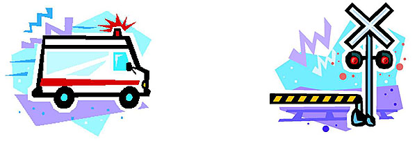
(Extended Text Description: This slide has two graphical illustrations. The first graphical illustration is an ambulance with its lightbar on, its siren on and moving quickly on the roadway, indicating the ambulance is responding to an incident. The second graphical illustration is a railroad crossing, with flashing red lights, warning noises, and a crossing arm down, indicating that a train is about to traverse across the roadway.)
Slide 18:

Slide 19:
Learning Objective #1
How can SCP directly improve the attractiveness of transit to travelers?
Answer Choices
- Lower cost of transit
- Improve reliability of service
- Provide more frequent transit service
- Improve passenger loads
Slide 20:
Learning Objective #1
Review of Answers
 a) Lower cost of transit
Incorrect. SCP may improve transit efficiency, but does not directly impact cost of transit to travelers.
 b) Improve reliability of service
Correct! SCP can reduce traffic signal delay and improve transit vehicle schedule adherence, resulting in improved reliability of service.
c) Provide more frequent transit service
Incorrect. With SCP and through more efficient run cutting, a transit agency may be able to provide more frequent transit service, but it is not a direct benefit.
d) Improve passenger loads
Incorrect. SCP does not directly impact the number of passengers on a vehicle, but rather impacts the vehicle’s on-time performance.
Slide 21:
Learning Objective #1
Summary of Learning Objective #1
Identify the Needs Addressed by and the Benefits of Signal Control Priority (SCP) on an Arterial
- The goal of an SCP system is to improve transportation operations by improving the overall efficiency of the street network for travelers and goods
- SCP improves transit operations by improving transit vehicle schedule adherence and efficiency
Slide 22:
Learning Objective #2: Identify the Components that Form an SCP System
- List the centers, vehicles, and field equipment that may be part of an SCP system
- Describe the functions of a Priority Request Generator (PRG), Priority Request Server (PRS), and Coordinator (CO)
Slide 23:
Learning Objective #2
List the Centers, Vehicles, and Field Equipment that may be Part of an SCP System
Primary Components of an SCP System
- Priority Request Generator (PRG)
- Priority Request Server (PRS)
- Coordinator (CO)
Slide 24:
Learning Objective #2
Describe the Functions of a Priority Request Generator (PRG), Priority Request Server
(PRS), and Coordinator (CO)
Priority Request Generator
- Alerts the traffic control system that a vehicle would like to receive priority
- Produces an estimated time of arrival for the vehicle to reach an intersection
- Produces an estimated time of departure for the vehicle to leave the intersection
- Sends a request for signal priority to the PRS
- Receives the status of a priority request from the PRS
Slide 25:
Learning Objective #2
Describe the Functions of a Priority Request Generator (PRG), Priority Request Server (PRS), and Coordinator (CO)
Priority Request Server
- Receives priority requests from PRGs, processes the request, and decides whether and how to grant priority based on the programmed strategies
- Prioritizes different priority requests
- Sends the status of priority requests back to the originating PRG
- Exchanges service requests and service request statuses with the CO
- Optionally, logs priority requests receives and sends contents of the log back to the traffic management center (TMC)
Slide 26:
Learning Objective #2
Describe the Functions of a Priority Request Generator (PRG), Priority Request Server
(PRS), and Coordinator (CO)
Coordinator
- Receives a service request from a PRS and implements the requested priority strategy based on the programmed strategies
- Sends the status of this service request back to the PRS
- Optionally, logs service requests received and sends contents of the log back to the TMC
Slide 27:
Learning Objective #2
List the Centers, Vehicles, and Field Equipment that may be Part of an SCP System
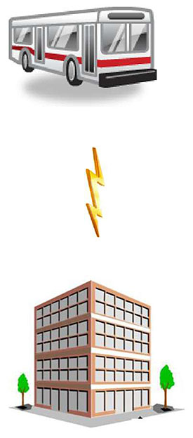
Secondary Components of an SCP System
-
Fleet Management Center (e.g., Transit Management Center)
- CAD/AVL
- Fleet Vehicle
- Traffic Management Center
- Management Station
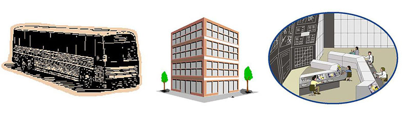
(Extended Text Description: This slide has three graphics. The first graphic is a transit bus. The second graphic is an office building used to depict a fleet management center. The third graphic is a traffic management center, with large monitors showing information and perhaps CCTV camera images forming one wall. In front of the wall are two rows of computer stations with 5 operators sitting in front of the computers and facing the large monitors.)
Slide 28:
Slide 29:
Learning Objective #2
Which of the following components determines which priority requests to service?
Answer Choices
- Priority Request Generator
- Priority Request Server
- Coordinator
- Transit Vehicle
Slide 30:
Learning Objective #2
Review of Answers
a) Priority Request Generator
Incorrect. A PRG generates the priority requests.
b) Priority Request Server
Correct! A PRS receives priority requests from PRGs, processes the request and decides whether and how to grant priority based on the programmed strategies.
c) Coordinator
Incorrect. A Coordinator receives service requests from a PRS and implements the priority strategy.
a) Transit Vehicle
Incorrect. The transit vehicle may generate a priority request, but it does not determine what priority request to service.
Slide 31:
Summary of Learning Objective #2
Identify the Components that form an SCP System
An SCP system consists of:
- Priority Request Generator (PRG) to generate the priority requests
- Priority Request Server (PRS) to determine which priority requests to service
- Coordinator (CO) to implement the service requests
An SCP system may also include:
- Fleet Management Center
- Fleet Vehicle
- Traffic Management Center
Slide 32:
Learning Objective #3: Describe the Different SCP System Architectures and the Considerations in Selecting an Architecture for Implementation
- Identify the different system architectures supported by the standards.
- Review the technical factors and institutional challenges that affect the selection of an SCP system architecture.
Slide 33:
Learning Objective #3
Identify the Different System Architectures Supported by the Standards
The system architecture for the SCP system to be implemented will depend on:
- Physical location of the PRG
- If the PRS is part of the signal controller or the traffic management software, or a separate physical entity
- The intermediary entities between the PRG and PRS, if any
- The communications infrastructure
Slide 34:
Learning Objective #3
Identify the Different System Architectures Supported by the Standards
Standards
- Support interoperability
- Minimize future integration costs
- Facilitate regional integration
- Makes procurements and testing easier
Slide 35:
Learning Objective #3
Identify the Different System Architectures Supported by the Standards
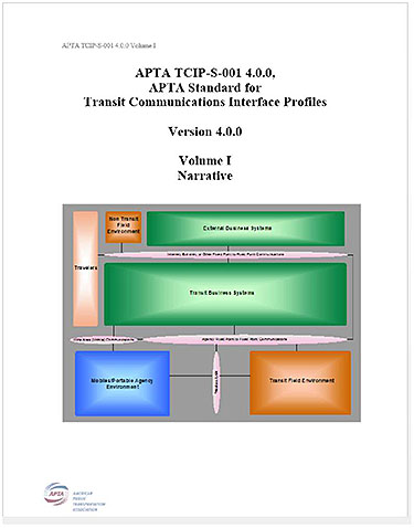
TCIP
- Transit Communications Interface Profiles
- Published by American Public Transportation Association (APTA)
- Defines standardized interfaces for the exchange of information (data) among transit business systems, subsystems, components, and devices
- Transit Signal Priority is 1 of 10 business processes defined
- Standardizes the interface primarily within the transit agency
Slide 36:
Learning Objective #3
Identify the Different System Architectures Supported by the Standards
NTCIP
NTCIP Family
-
NTCIP (National Transportation Communications for ITS Protocols): a family of standards for the ITS industry
- Provides rules for communicating (called protocols)
- Provides the vocabulary (called objects) necessary to control traffic field equipment

(Extended Text Description: This slide has the logos of American Association of State and Highway Transportation Officials (AASHTO), Institute of Transportation Engineers (ITE), and National Electrical Manufacturers Association (NEMA).)
Slide 37:
Learning Objective #3
Identify the Different System Architectures Supported by the Standards
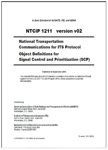
NTCIP 1211
- Information Content Standard
- Standardizes the interface between some of the components of an SCP system
Slide 38:
Learning Objective #3
Identify the Different System Architectures Supported by the Standards
System Architecture
- Describes the overall framework of the (SCP) system, including the physical components and the logical entities
- TCIP defines five system architectures
- NTCIP 1211 v02 defines the same system architectures plus one additional
- These represent only some of the more common systems architectures of an SCP system
Slide 39:
Learning Objective #3
Identify the Different System Architectures Supported by the Standards
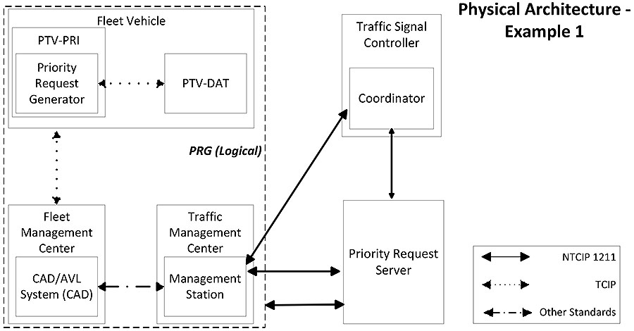
(Extended Text Description: This slide contains a diagram showing the interfaces between different components of an SCP system. The diagram is labeled Physical Architecture - Example 1. At the bottom right corner of the diagram is a legend. The legend shows that a solid line between components represents an interface that is addressed by the NTCIP 1211 standard. A dotted line between components represents an interface that is addressed by the TCIP standard. A dotted - dashed line between components represents an interface that is addressed by other standards. The upper left corner of the diagram is a box entitled Fleet Vehicle. Within the Fleet Vehicle box are two boxes, one entitled PTV-PRI and one entitled PTV-DAT. Within the PTV-PRI box is another box entitled Priority Request Generator. There is a dotted line, with an arrow on both ends, between the Priority Request Generator and the PTV-DAT. Below the Fleet Vehicle Box is a box entitled Fleet Management Center. Within the Fleet Management Center box is a box entitled CAD/AVL System (CAD). There is a dotted-dashed line, with an arrow on both ends, between the CAD/AVL System and the Management Station. The Fleet Management Center and Traffic Management Center boxes are within a dashed box entitled PRG (Logical). To the right of the Traffic Management Center box, and outside the dashed box, is a box entitled Priority Request Server. Above the Priority Request Server box is a box entitled Traffic Signal Controller. Within the Traffic Signal Controller is a box entitled the Coordinator. There is a solid line, with an arrow on both ends, between the Management Station and the Priority Request Server. There is a solid line, with an arrow on both ends, between the Management Station and the Coordinator. There is a solid line, with an arrow on both ends, between the Priority Request Server and the Coordinator. There is a solid line, with an arrow on both ends, between the PRG (Logical) and the Priority Request Server.)
Slide 40:
Learning Objective #3
Identify the Different System Architectures Supported by the Standards
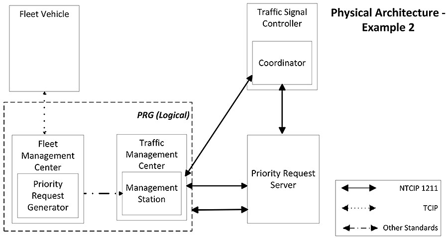
(Extended Text Description: This slide contains a diagram showing the interfaces between different components of an SCP system. The diagram is labeled Physical Architecture - Example 2. At the bottom right corner of the diagram is a legend. The legend shows that a solid line between components represents an interface that is addressed by the NTCIP 1211 standard. A dotted line between components represents an interface that is addressed by the TCIP standard. A dotted - dashed line between components represents an interface that is addressed by other standards. The upper left corner of the diagram is a box entitled Fleet Vehicle. Below the Fleet Vehicle Box is a box entitled Fleet Management Center. Within the Fleet Management Center box is a box entitled Priority Request Generator. There is a dotted line, with an arrow on both ends, between the Fleet Vehicle and the Priority Request Generator. To the right of the Fleet Management Center is a box entitled Traffic Management Center. Within the Traffic Management Center box is a box entitled Management Station. There is a dotted-dashed line, with an arrow on both ends, between the Priority Request Generator and the Management Station. The Fleet Management Center and Traffic Management Center boxes are within a dashed box entitled PRG (Logical). To the right of the Traffic Management Center box, and outside the dashed box, is a box entitled Priority Request Server. Above the Priority Request Server box is a box entitled Traffic Signal Controller. Within the Traffic Signal Controller is a box entitled the Coordinator. There is a solid line, with an arrow on both ends, between the Management Station and the Priority Request Server. There is a solid line, with an arrow on both ends, between the Management Station and the Coordinator. There is a solid line, with an arrow on both ends, between the Priority Request Server and the Coordinator. There is a solid line, with an arrow on both ends, between the PRG (Logical) and the Priority Request Server.)
Slide 41:
Learning Objective #3
Identify the Different System Architectures Supported by the Standards
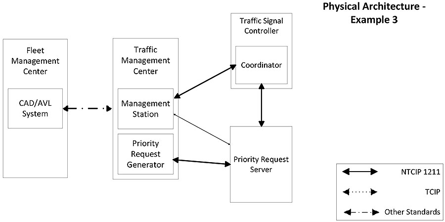
(Extended Text Description: This slide contains a diagram showing the interfaces between different components of an SCP system. The diagram is labeled Physical Architecture - Example 3. At the bottom right corner of the diagram is a legend. The legend shows that a solid line between components represents an interface that is addressed by the NTCIP 1211 standard. A dotted line between components represents an interface that is addressed by the TCIP standard. A dotted - dashed line between components represents an interface that is addressed by other standards. The left side of the diagram is a box entitled Fleet Management Center. Within the Fleet Management Center box is a box entitled CAD/AVL System. To the right of the Fleet Management Center is a box entitled Traffic Management Center. Within the Traffic Management Center box are two boxes. One box is entitled Management Station and the second box is entitled Priority Request Generator. There is a dotted/dashed line, with an arrow on both ends, between the CAD/AVL System and the Traffic Management Center. To the right of the Traffic Management Center is a box entitled Priority Request Server. Above the Priority Request Server box is a box entitled Traffic Signal Controller. Within the Traffic Signal Controller is a box entitled the Coordinator. There is a solid line, with an arrow on both ends, between the Priority Request Generator and the Priority Request Server. There is a solid line, with an arrow on both ends, between the Management Station and the Priority Request Server. There is a solid line, with an arrow on both ends, between the Management Station and the Coordinator. There is a solid line, with an arrow on both ends, between the Priority Request Server and the Coordinator.)
Slide 42:
Learning Objective #3
Identify the Different System Architectures Supported by the Standards
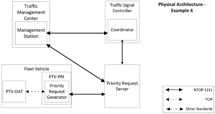
(Extended Text Description: This slide contains a diagram showing the interfaces between different components of an SCP system. The diagram is labeled Physical Architecture - Example 4. At the bottom right corner of the diagram is a legend. The legend shows that a solid line between components represents an interface that is addressed by the NTCIP 1211 standard. A dotted line between components represents an interface that is addressed by the TCIP standard. A dotted - dashed line between components represents an interface that is addressed by other standards. The lower left corner of the diagram is a box entitled Fleet Vehicle. Within the Fleet Vehicle box are two boxes, one entitled PTV-PRI and one entitled PTV-DAT. Within the PTV-PRI box is another box entitled Priority Request Generator. There is a dotted line, with an arrow on both ends, between the Priority Request Generator and the PTVDAT. To the right of the Fleet Vehicle is a box entitled Priority Request Server. Above the Priority Request Server box is a box entitled Traffic Signal Controller. Within the Traffic Signal Controller is a box entitled the Coordinator. There is a solid line, with an arrow on both ends, between the Priority Request Generator and the Priority Request Server. There is a solid line, with an arrow on both ends, between the Priority Request Server and the Coordinator. Above the Fleet Vehicle box is a box entitled Traffic Management Center. Within the Traffic Management Center box is a box entitled Management Station. There is a solid line, with an arrow on both ends, between the Management Station and the Priority Request Server. There is a solid line, with an arrow on both ends, between the Management Station and the Coordinator.)
Slide 43:
Learning Objective #3
Identify the Different System Architectures Supported by the Standards
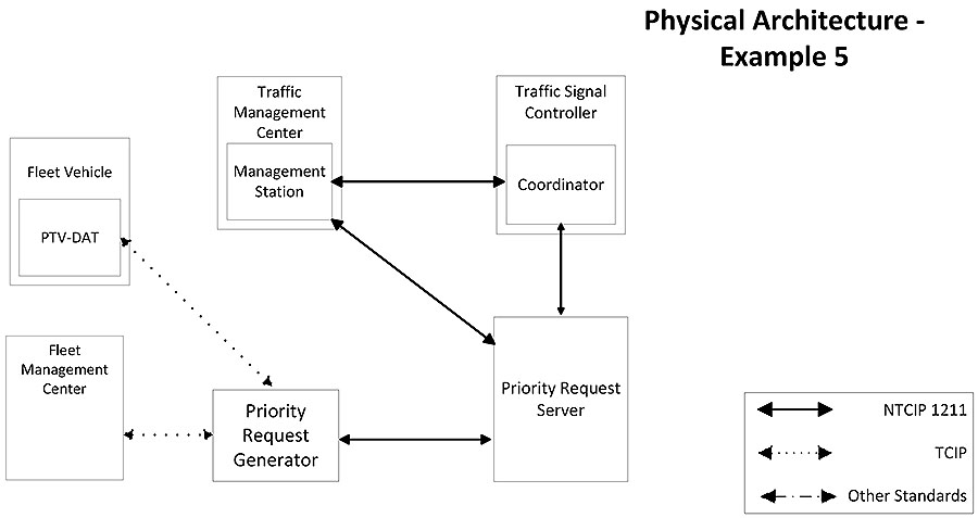
(Extended Text Description: This slide contains a diagram showing the interfaces between different components of an SCP system. The diagram is labeled Physical Architecture - Example 5. At the bottom right corner of the diagram is a legend. The legend shows that a solid line between components represents an interface that is addressed by the NTCIP 1211 standard. A dotted line between components represents an interface that is addressed by the TCIP standard. A dotted - dashed line between components represents an interface that is addressed by other standards. The upper left corner of the diagram is a box entitled Fleet Vehicle. Within the Fleet Vehicle box is a box entitled PTV-DAT. Below the Fleet Vehicle is a box entitled Fleet Management Center. To the right of the Fleet Management Center is a box entitled Priority Request Generator. There is a dotted line, with an arrow on both ends, between the PTV-DAT and the Priority Request Generator. There is also a dotted line, with an arrow on both ends, between the Fleet Management Center and the Priority Request Generator. To the right of the Priority Request Generator is a box entitled Priority Request Server. Above the Priority Request Server box is a box entitled Traffic Signal Controller. Within the Traffic Signal Controller is a box entitled the Coordinator. There is a solid line, with an arrow on both ends, between the Priority Request Generator and the Priority Request Server. There is a solid line, with an arrow on both ends, between the Priority Request Server and the Coordinator. Above the Priority Request Generator is a box entitled Traffic Management Center. Within the Traffic Management Center box is a box entitled Management Station. There is a solid line, with an arrow on both ends, between the Management Station and the Priority Request Server. There is a solid line, with an arrow on both ends, between the Management Station and the Coordinator.)
Slide 44:
Learning Objective #3
Identify the Different System Architectures Supported by the Standards
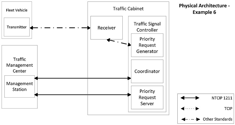
(Extended Text Description: This slide contains a diagram showing the interfaces between different components of an SCP system. The diagram is labeled Physical Architecture - Example 6. At the bottom right corner of the diagram is a legend. The legend shows that a solid line between components represents an interface that is addressed by the NTCIP 1211 standard. A dotted line between components represents an interface that is addressed by the TCIP standard. A dotted - dashed line between components represents an interface that is addressed by other standards. The upper left corner of the diagram is a box entitled Fleet Vehicle. Within the Fleet Vehicle box is a box entitled Transmitter. Below the Fleet Vehicle is a box entitled Traffic Management Center. To the right of the Traffic Management Center is a box entitled Traffic Cabinet. There are two boxes within the Traffic Cabinet. One box is entitled Receiver. The second box is entitled Traffic Signal Controller. Within the Traffic Signal Controller are three boxes. One box is entitled Priority Request Generator, the second box is entitled Coordinator, and the third box is entitled Priority Request Server. There is a dotted-dash line, with an arrow on both ends, between the Transmitter and Receiver. There is a dotted-dash line, with an arrow on both ends, between the Receiver and the Priority Request Generator. There is also a solid line, with an arrow on both ends, between the Management Stations and the Priority Request Server. There is a solid line, with an arrow on both ends, between the Management Station and the Coordinator.)
Slide 45:
Learning Objective #3
Review the Technical Factors and Institutional Challenges that Affect the Selection of an SCP System Architecture
The selection of an SCP system architecture may depend on a number of factors, including technical factors and institutional challenges.
Technical factors include:
- Signal system capabilities
- Fleet vehicle capabilities
- Communications infrastructure
Institutional factors may include:
- Does the SCP cross institutional boundaries?
- Are priority requests initiated at the vehicle or center level?
Slide 46:

Slide 47:
Learning Objective #3
What is not a significant factor in selecting an architecture for an SCP System?
Answer Choices
- Communications Infrastructure
- Current capabilities on the transit vehicle
- Current capabilities of the transit vehicle driver
- Current capabilities of the traffic signal controller
Slide 48:
Learning Objective #3
Review of Answers
a) Communications Infrastructure
Incorrect. The current communications infrastructure can play a role in selecting a system architecture.
b) Current capabilities on the transit vehicle
Incorrect. This is an important factor for selecting a system architecture, particularly depending on whether the transit vehicle has AVL.
c) Current capabilities of the transit vehicle driver
Correct! All of the functions of the SCP system can be automated without any intervention or input from the driver.
d) Current capabilities of the traffic signal controller
Incorrect. The capabilities of traffic system controller is extremely important - this plays a large role in infrastructure costs.
Slide 49:
Summary of Learning Objective #3
Describe the Different SCP System Architectures and the Considerations in Selecting an Architecture for Implementation
The standards describe several system architectures, which identifies the relationships between the different components of an
SCP system.
Selection of a system architecture involves an evaluation of:
- Goals and objectives
- Capabilities of the signal controllers and fleet vehicles
- Communications infrastructure
- Institutional factors
Slide 50:
Learning Objective #4: Identify the Interfaces in an SCP System and the ITS Standards that Addresses each of these Interfaces
- Identify the interfaces addressed by the TCIP Standard
- Identify the interfaces addressed by the NTCIP Standards
Slide 51:
Learning Objective #4
Identify the Interfaces Addressed by the TCIP Standard
ITS Standards
Define how ITS components interact and exchange information-
Benefits of ITS Standards:
- Supports interoperability
- Lowers integration costs
- Makes procurements and testing easier
Slide 52:
Learning Objective #4
Identify the Interfaces Addressed by the TCIP Standard
TCIP Interfaces
Interfaces addressed by the TCIP standards include:
-
Between the Public Transit Vehicle - DATa manager (PTV-DAT) and the Public Transit Vehicle - PRIority (PTV-PRI)
- PTV-DAT - logical entity on the PTV responsible for data management
- PTV-PRI - logical entity responsible on the PTV for signal priority functions
- Between the PTV-PRI and the Computer Aided Dispatching/Automatic Vehicle Location (CAD/AVL) System
- Between the PTV-DAT and a Roadside PRG
Slide 53:
Learning Objective #4
Identify the Interfaces Addressed by the
NTCIP Standards
Interfaces addressed by the NTCIP standards include:
- Interfaces between traffic control equipment and transportation management centers
- Interfaces between traffic control equipment and fleet vehicles
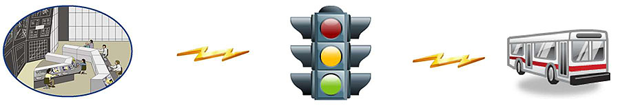
(Extended Text Description: This has a graphical illustration depicting a traffic signal communicating (or exchanging information) with a transit bus, and the same traffic signal communicating (or exchanging information) with a traffic management center. The traffic management center is represented by a graphic with large monitors showing information and perhaps CCTV camera images forming one wall. In front of the wall are two rows of computer stations with 5 operators sitting in front of the computers and facing the large monitors.)
Slide 54:
Learning Objective #4
Identify the Interfaces Addressed by the
NTCIP Standards
The following are the interfaces addressed by NTCIP 1211:
- Between a management station and a PRS
- Between a management station and a CO
- Between a PRG and a PRS, and
- Between a PRS and a CO
Slide 55:

Slide 56:
Learning Objective #4
Which is not a benefit of using ITS
Standards?
Answer Choices
- Supports interoperability
- Eliminates institutional issues
- Lowers integration costs
- Makes procurements easier
Slide 57:
Learning Objective #4
Review of Answers
a) Supports interoperability
Incorrect. ITS Standards support interoperability, which help keep users from being limited to a single vendor’s products when deploying more devices.
b) Eliminates institutional issues
Correct! ITS Standards helps with resolving and mitigating technical issues, but not institutional issues.
c) Lowers integration costs
Incorrect. ITS Standards lower integration costs by providing a common language between systems that are being integrated.
d) Makes procurements easier
Incorrect. ITS standards make procurements, as well as testing, easier by defining the language used by ITS devices.
Slide 58:
Summary of Learning Objective #4
Identify the Interfaces in an SCP System and the ITS Standards that Addresses Each of these Interfaces
- TCIP standards address interfaces between transportation management centers and fleet vehicles, and between logical entities within the fleet vehicles, such as the CAD/AVL system on a transit vehicle
- The NTCIP 1211 standard addresses the interfaces between specific components of an SCP system
Slide 59:
Learning Objective #5: Identify the User Needs Addressed by the Standards
- Identify architectural needs addressed by the standards
- Identify the features addressed by the standards
Slide 60:
Learning Objective #5
Identify Architectural Needs Addressed by the Standards
SCP operational needs may vary depending on physical architecture used to implement the system
The following operational needs should be considered when implementing an SCP system:
-
Integral entities
- E.g., the functions of the PRS and the CO may be physically within the same traffic signal controller
- Provide live data
-
Support multiple instances of an entity
- i.e., needs to support requests from multiple PRGs
-
Provide compressed data
- Bandwidth efficient
Slide 61:
Learning Objective #5
Identify the Features Addressed by the Standards
NTCIP 1211 user needs, or features, are organized by the interface they address:
- Management station to PRS
- Management station to CO
- PRG to PRS
- PRS to CO
Slide 62:
Learning Objective #5
Identify the Features Addressed by the Standards
Features supported between a management station and a PRS:
-
Manage the PRS
- Determine PRS Identity
- Determine PRS Configuration
- Configure Reservice Period
- Configure Time to Live Period
- PRS Clock Synchronization
- Determine Priority Request Criteria
- Monitor the PRS
- Retrieve Log Data from the PRS
Slide 63:
Learning Objective #5
Identify the Features Addressed by the Standards
Features supported between a management station and a CO:
- Configure Priority Strategies
- Determine Priority Strategies
- Monitor the CO
- Retrieve Log Data from the CO
Slide 64:
Learning Objective #5
Identify the Features Addressed by the Standards
Features supported between the PRG and the PRS:
-
Exchange Priority Requests
- The PRG sends priority requests to the PRS
-
Exchange Priority Request Status
- The PRS sends the status of a priority request to the PRG
Slide 65:
Learning Objective #5
Identify the Features Addressed by the Standards
Features supported between a PRS and a CO:
-
Exchange Service Requests
- The PRS sends a service request to a CO, specifying a priority strategy to be implemented, the time of service requested, and the estimated time of departure
-
Exchange Service Request Status
- The CO returns the status of a service request to the PRS
Slide 66:

Slide 67:
Learning Objective #5
Which of the following user needs are not supported by NTCIP 1211 v02?
Answer Choices
- Need to know the distance of the transit vehicle from the intersection
- Need to configure priority strategies
- Need to exchange priority requests
- Need to exchange service requests
Slide 68:
Learning Objective #5
Review of Answers
a) Need to know the distance of the transit vehicle from the intersection
Correct! This need is not addressed by NTCIP 1211 v02. However, it may be addressed by TCIP.
b) Need to configure priority strategies
Incorrect. This need is addressed as part of the interface between a management station and a CO.
c) Need to exchange priority requests
Incorrect. This need is addressed as part of the interface between a priority request generator and a priority request server.
d) Need to exchange service requests
Incorrect. This need is addressed as part of the interface between a priority request server and a coordinator.
Slide 69:
Learning Objective #5
What do the ITS standards define?
Answer Choices
- The conditions that must be satisfied for the PRG to generate a priority request
- The process that the PRS prioritizes priority requests
- How the CO implements the priority strategy
- The interfaces between the components of an SCP system
Slide 70:
Learning Objective #5
Review of Answers
a) The conditions that must be satisfied for the PRG to generate a priority request
Incorrect. Standards do not define the conditions for the PRG to generate a priority request - that is specific to each implementation.
b) The process that the PRS prioritizes priority requests
Incorrect. The process and how the PRS prioritizes priority request is also implementation specific.
c) How the CO implements the priority strategy
Incorrect. How the CO implements the priority strategy is also implementation specific
d) The interfaces between the components of an SCP system
Correct! The standards defines the interfaces between the components—what information is exchanged and how.
Slide 71:
Summary of Learning Objective #5
Identify the User Needs Addressed by the Standards
- SCP architectural needs vary depending on the physical architecture to be implemented
- SCP user needs are organized by the interface they address
Slide 72:
Learning Objective #6: Describe at a High Level how to Incorporate ITS Standards into an SCP System Procurement
- Present a case study where ITS Standards were incorporated in an SCP system procurement
Slide 73:
Learning Objective #6
Identify a Case Study where ITS Standards were Incorporated in an SCP System Procurement
Current Situation
-
The Alphaville Transit Agency
- experiencing increasing travel times on one of its routes
- Due to recurring and non-recurring congestion
- Transit signal priority (TSP) will help improve travel time reliability
- Vehicles already equipped with AVL and radio communications
- Far-side and near-side transit stops
Slide 74:
Learning Objective #6
Identify a Case Study where ITS Standards were Incorporated in an SCP System Procurement
Current Situation (cont.)
-
Traffic agency
- Planning to upgrade the signal controllers
- Concerned about maintaining traffic flow but willing to provide signal priority
- On the City’s fiber optic network
- Existing communications links with each controller
Slide 75:
Learning Objective #6
Identify a Case Study where ITS Standards were Incorporated in an SCP System Procurement
Goals
- The primary goal is to increase travel time reliability
- A secondary goal is to decrease travel times
- Performance measures are desired to verify benefits because the Transit Agency has identified other corridors that may benefit from transit signal priority

Slide 76:
Learning Objective #6
Identify a Case Study where ITS Standards were Incorporated in an SCP System Procurement
Institutional Issues
- Develop an agreement
-
Agree on the conditions for providing priority
- A vehicle is more than two minutes behind schedule
- Does not have to be a revenue run
- Conditions allow for queue jump

Slide 77:
Learning Objective #6
Identify a Case Study where ITS Standards were Incorporated in an SCP System Procurement
Traffic Agency Capabilities
-
The traffic agency is upgrading several, but not all, of the traffic signal controllers along the arterial
- The traffic agency agreed to adjust their procurement specifications for new signal controllers to support transit signal priority
- The new signal controllers will include the functions of an CO
- For signalized intersections not scheduled to be replaced with new traffic signal controllers, a device may need to be installed at the signal controller cabinet
Slide 78:
Learning Objective #6
Identify a Case Study where ITS Standards were Incorporated in an SCP System Procurement
Cost Analysis
-
Based on the cost analysis, the PRG should be located in the transit dispatch center
- The transit dispatch center system constantly knows the location of each transit vehicles because of the AVL system
- The transit dispatch center system knows the schedule for each transit vehicle and can maintain the performance measures
Slide 79:
Learning Objective #6
Identify a Case Study where ITS Standards were Incorporated in an SCP System Procurement
Cost Analysis
-
Based on the cost analysis, the PRS is determined to be located in the traffic management center
- The PRS knows the operating status of the traffic signal controllers
- The dispatch center sends the priority request to the PRS in the TMC. The PRS will consider all the priority requests along the corridor and select the appropriate strategy(ies). The TMC will then forward the strategy to the CO
- Low cost because it takes advantage of the existing communications infrastructure and most processing is performed at the centers, minimizing costs for equipment on individual vehicles or intersections
Slide 80:
Learning Objective #6
Identify a Case Study where ITS Standards were Incorporated in an SCP System Procurement
User Needs
Review the user needs supported by the standards. Determine if each user need is applicable to the corridor.
-
Management Station to PRS
- Manage the PRS
- Determine Priority Request Criteria
- Monitor the PRS
- Retrieve the Log Data from the PRS Not Selected
Slide 81:
Learning Objective #6
Identify a Case Study where ITS Standards were Incorporated in an SCP System Procurement
User Needs (cont.)
-
Management Station to CO
- Configure Priority Strategies
- Determine Priority Strategies
- Monitor the CO
- Retrieve Log Data from the CO
Slide 82:
Learning Objective #6
Identify a Case Study where ITS Standards were Incorporated in an SCP System Procurement
User Needs
Review the user needs supported by the standards. Determine if each user need is applicable to the corridor.
-
PRG to PRS
- Exchange Priority Requests
- Exchange Priority Request Status
-
PRS to CO
- Exchange Service Requests
- Exchange Service Request Status
Slide 83:
Learning Objective #6
Identify a Case Study where ITS Standards were Incorporated in an SCP System Procurement
Other Changes
- Near-side bus stops require significantly more information for transit signal priority
- Green extension more valuable than early green
- Can’t make significant timing adjustments in some environments
- Tuned schedules to capture value of TSP on a reliable manner
Slide 84:
Learning Objective #6
Summary of Learning Objective #6
Describe at a High Level how to Incorporate ITS Standards into an SCP System Procurement.
ITS Standards can be used:
- To identify the scope of an SCP System
- To determine the features of an SCP system
Slide 85:
Learning Objective #7: Describe Other Arterial Management Tools and Strategies
- Define the purpose of an integrated corridor management (ICM)
- Describe how transit traveler information improves transit service along arterials
Slide 86:
Learning Objective #7
Define the Purpose of an Integrated Corridor Management
Integrated Corridor Management (ICM)
- Allows institutional partner agencies to manage multi-modal transportation corridors as a system rather than as individual assets.
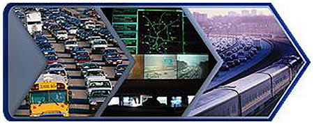
(Extended Text Description: This slide has three photographs contained within an arrow icon. The first photograph is of congested traffic on a highway. The second photograph is a traffic management center with large monitors on a wall and a bank of computer stations in front on a wall. One monitor on the wall is displaying a map showing the highway network, another monitor on the wall is showing informational text, and 3 additional monitors on the wall are showing CCTV camera images of traffic conditions on the highway. The third photograph is of a commuter railroad train in front of the highway with congested traffic.)
Slide 87:
Learning Objective #7
Define the Purpose of an Integrated Corridor Management
Integrated Corridor Management (ICM)
Manage corridor as an integrated asset in order to:
- Improve travel time reliability and predictability
- Manage congestion
- Empower travelers through better information and choices
- Improve incident response times
- Reduce the impacts of incidents on transportation operations
- May require integration of multiple ITS Standards
Slide 88:
Learning Objective #7
Define the Purpose of an Integrated Corridor Management
Integrated Corridor Management (ICM)
Other Standards
- TCIP - manage transit assets
- NTCIP - manage traffic devices (traffic signals, dynamic message signs, ramp meters)
- TMDD - center-to-center communications
- https://www.its.dot.gov/icms/ for more information
Slide 89:
Learning Objective #7
Describe How Transit Traveler Information Improves Transit Service Along Arterials
Transit Traveler Information
Transit traveler information can improve transit service along arterials by:
- Providing travelers with information about alternatives
- Managing traveler expectations
- Increased sense of system reliability
(Extended Text Description: This slide has three graphics. The first graphic is a touch screen kiosk for viewing information. The second graphic is a timetable showing the arrival time of 16:25. The third graphic is of a smartphone with an antenna, and several buttons.)
Slide 90:
Learning Objective #7
Describe How Transit Traveler Information Improves Transit Service Along Arterials
Transit Traveler Information
Other Standards
- GTFS - General Transit Feed Specification - for schedule information
- NTCIP 1203 - Dynamic Message Signs
- TMDD - center-to-center communications
Slide 91:

Slide 92:
Learning Objective #7
Which of the following is NOT a characteristic of an ICM program?
Answer Choices
- Sharing information between agencies
- Coordinating between different modes of transportation
- Providing traveler information
- Improving maintenance of transit vehicles
Slide 93:
Learning Objective #7
Review of Answers
Sharing information between agencies
Incorrect. The goal is ICM is to optimize the entire transportation network by leveraging unused capacity along corridors. This is accomplished by sharing information between transportation agencies.
Coordinating between different modes of transportation
Incorrect. Coordinating between different transportation modes is a key component of the ICM program.
Providing traveler information
Incorrect. Providing traveler information allows travelers to make better informed choices that can impact the level of congestion on the transportation network.
Improving maintenance of transit vehicles
Correct! Maintenance of transit vehicle is the responsibility of the operating agency.
Slide 94:
Summary of Learning Objective #7
Describe Other Arterial Management Tools and Strategies
Other arterial management strategies include:
- ICM, where regional agencies collaborate to manage a corridor as a system, rather than as separate assets
- Transit traveler information, including real-time traveler information, such as bus arrival times and incident notifications
Slide 95:
What We Have Learned
- Signal control priority is an operational strategy to facilitate the movement of fleet vehicles through signalized intersections.
-
A signal control priority system consists of:
- A priority request generator
- A priority request server
- A controller
- Technical factors for the selection of a system architecture include signal system and fleet vehicle capabilities and communications.
- ITS Standards can be used to design, procure, and operate a signal control priority system
- Integrated corridor management strategies and transit traveler information can improve service along a transportation corridor.
Slide 96:
Resources
- NTCIP 1202 v2.19 - Object Definitions for Actuated Signal Controllers (ASC): https://www.ntcip.org/
- NTCIP 1211 v2.24 - Object Definitions for Signal Control and Prioritization: https://www.ntcip.org/
- Transit Communications Interface Profiles (TCIP) Standard Development Program: https://www.apta.com/research-technical-resources/standards/technology/apta-tcip-s-001-4-1-1/
- Transit Signal Priority (TSP): A Planning and Implementation Handbook: https://nacto.org/docs/usdg/transit_signal_priority_handbook_smith.pdf
- TCIP Volume 1: http://www.aptatcip.com/Documents.htm- content is no longer available.
Slide 97:
Next Course Module
Module 9:
Arterial Management and Transit Signal Priority: Specifying Requirements for SCP based on NTCIP 1211 Standard, Part 2 of 2
- Builds on the content of Module 8
- Provides detailed information on how to identify and use applicable ITS standards to procure and operate a signal control priority system following a Systems Engineering process
- Focuses on using the tools provided with NTCIP 1211 - Object Definitions for Signal Control and Prioritization Standard v02
Slide 98:
Thank you for completing this module.