ITS Transit Standards Professional Capacity Building Program
Module 9: Arterial Management and Transit Signal Priority: Specifying Requirements for Signal Control Priority (SCP) Based on NTCIP 1211 Standard, Part 2 of 2
HTML of the PowerPoint Presentation
(Note: This document has been converted from a PowerPoint presentation to 508-compliant HTML. The formatting has been adjusted for 508 compliance, but all the original text content is included, plus additional text descriptions for the images, photos and/or diagrams have been provided below.)
Slide 1:
(Extended Text Description: Welcome - Graphic image of introductory slide. A large dark blue rectangle with a wide, light grid pattern at the top half and bands of dark and lighter blue bands below. There is a white square ITS logo box with words "Standards ITS Training" in green and blue on the middle left side. The word "Welcome" in white is to the right of the logo. Under the logo box is the logo for the U.S. Department of Transportation, Office of the Assistant Secretary for Research and Technology.)
Slide 2:
(Extended Text Description: This slide, entitled "Mac Lister" has a photo of Mac Lister, Program Manager Knowledge and Technology Transfer, ITS Joint Program Office, on the left hand side, with his email address, Mac.Lister@dot.gov. A screen capture snapshot of the home webpage is found on the right hand side - for illustration only - from August 2014. Below this image is a link to the current website: www.its.dot.gov/pcb - this screen capture snapshot shows an example from the Office of the Assistant Secretary for Research and Development - Intelligent Transportation Systems Joint Program Office - ITS Professional Capacity Building Program/Advanced ITS Education. Below the main site banner, it shows the main navigation menu with the following items: About, ITS Training, Knowledge Exchange, Technology Transfer, ITS in Academics, and Media Library. Below the main navigation menu, the page shows various content of the website, including a graphic image of professionals seated in a room during a training program. A text overlay has the text Welcome to ITS Professional Capacity Building. Additional content on the page includes a box entitled What's New and a section labeled Free Training. Again, this image serves for illustration only. The current website link is: https://www.its.dot.gov/pcb.)
Slide 3:
(Extended Text Description: This slide, entitled "Jeffrey Spencer" has a photo of Jeffrey Spencer, ITS Team Leader, Federal Transit Administration, Office of Research, Demonstration and Innovation, on the left hand side, with his email address, Jeffrey.Spencer@dot.gov. A screen capture snapshot of the home webpage is found on the right hand side - for illustration only - which is the same screen snapshot from Slide 2. Below this image and to the right is the Federal Transit Administration (FTA) logo.)
Slide 4:
ITS Transit Standards Professional Capacity Building Program
Module 9:
Arterial Management and Transit Signal Priority: Specifying Requirements for Signal Control Priority (SCP) Based on NTCIP 1211 Standard, Part 2 of 2
Slide 5:

Slide 6:
Instructor
Patrick Chan, P.E.
Senior Technical Staff
Consensus Systems Technologies
Flushing, NY, USA
Slide 7:
Target Audience
- Transit planning, operations, and maintenance staff;
- Traffic management operations staff;
- Transit and traffic procurement staff;
- Specification writers;
- Transit electronic systems maintenance staff;
- Integrated Corridor Management project and operations team;
- Transit technology vendors; and
- Transit ITS contractors and consultants.
Slide 8:
Recommended Prerequisite(s)
| Decision-Maker | Project Manager | Project Engineer | |
|---|---|---|---|
| Module 1: Introduction to ITS Transit Standards | N/A | ✓ | ✓ |
| Module 2: Transit Management Standards, Part 1 of 2 | N/A | ✓ | ✓ |
| Module 3: Transit Communications Interface Profiles (TCIP), Part 1 of 2 | N/A | ✓ | ✓ |
| Module 4: Transit Communications Interface Profiles (TCJP), Part 2 of 2 | N/A | ✓ | ✓ |
| Module 5: Transit Management Standards, Part 2 of 2 | N/A | ✓ | ✓ |
| Module 8: Arterial Management and Transit Signal Priority, Part 1 of 2 | N/A | ✓ | ✓ |
Slide 9:
Curriculum Path (Project Manager)
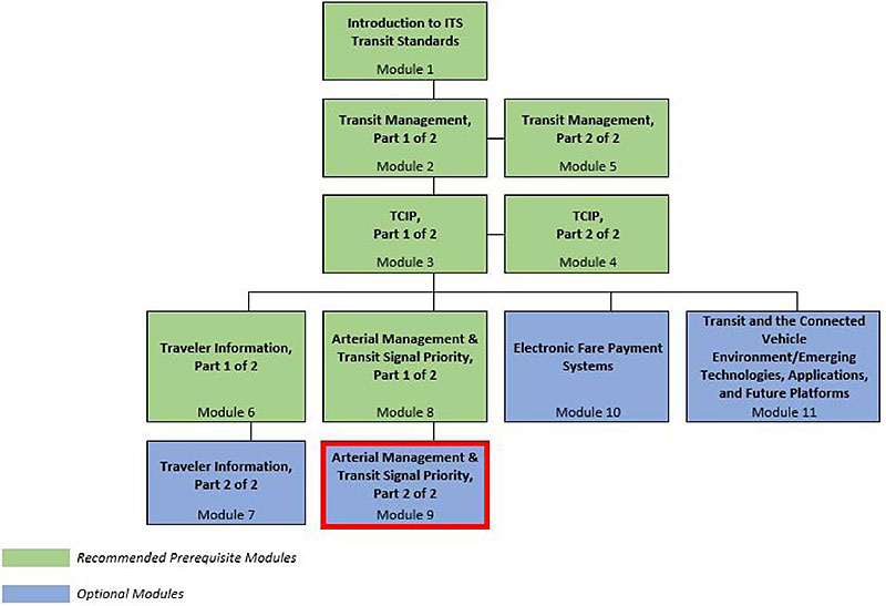
(Extended Text Description: This slide, entitled "Curriculum Path (Project Manager)," contains a graphical illustration indicating the sequence of training modules that lead up to and follow each course. Each module is represented by a box with the name of the module on top, and the module number below. A green box indicates that the module is a recommended pre-requisite Module. A blue box indicates that the module is an optional module. The top row contains one green box entitled "Introduction to ITS Transit Standards: Module 1." A line leads from the Module 1 box down one row to a green box entitled "Transit Management, Part 1 of 2: Module 2." A line leads from the Module 2 box to a green box to its right entitled "Transit Management, Part 2 of 2: Module 5." A line also leads down one row from the Module 2 box to a green box entitled "TCIP, Part 1 of 2: Module 3." A line leads from the Module 3 box to a green box to its right entitled "TCIP, Part 2 of 2: Module 4." A line also leads from the Module 3 box downward to a horizontal line, which contains four branching vertical lines, each leading down to one of four boxes on the next (fourth) row. The first, or leftmost, box on the fourth row is a green box entitled "Traveler Information, Part 1 of 2: Module 6." The second box on the fourth row is a green box entitled "Arterial Management & Transit Signal Priority, Part 1 of 2: Module 8." The third box on the fourth row is a blue box entitled "Electronic Fare Payment Systems: Module 10." The fourth box on the fourth row is a blue box entitled "Transit and the Connected Vehicle Environment/ Emerging Technologies, Applications, and Future Platforms: Module 11." A line leads from the Module 6 box down one row to a blue box entitled "Traveler Information, Part 2 of 2: Module 7." A line leads from the Module 8 box down one row to a blue box entitled" Arterial Management & Transit Signal Priority, Part 2 of 2: Module 8.")
Slide 10:
Curriculum Path (Project Engineer)
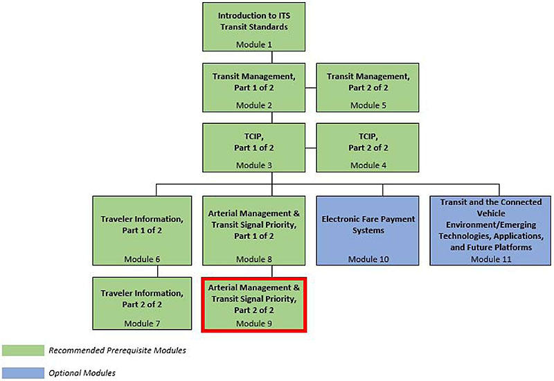
(Extended Text Description: This slide, entitled "Curriculum Path (Project Engineer)," contains a graphical illustration indicating the sequence of training modules that lead up to and follow each course. Each module is represented by a box with the name of the module on top, and the module number below. A green box indicates that the module is a recommended pre-requisite Module. A blue box indicates that the module is an optional module. The top row contains one green box entitled "Introduction to ITS Transit Standards: Module 1." A line leads from the Module 1 box down one row to a green box entitled "Transit Management, Part 1 of 2: Module 2." A line leads from the Module 2 box to a green box to its right entitled "Transit Management, Part 2 of 2: Module 5." A line also leads down one row from the Module 2 box to a green box entitled "TCIP, Part 1 of 2: Module 3." A line leads from the Module 3 box to a green box to its right entitled "TCIP, Part 2 of 2: Module 4." A line also leads from the Module 3 box downward to a horizontal line, which contains four branching vertical lines, each leading down to one of four boxes on the next (fourth) row. The first, or leftmost, box on the fourth row is a green box entitled "Traveler Information, Part 1 of 2: Module 6." The second box on the fourth row is a green box entitled "Arterial Management & Transit Signal Priority, Part 1 of 2: Module 8." The third box on the fourth row is a blue box entitled "Electronic Fare Payment Systems: Module 10." The fourth box on the fourth row is a blue box entitled "Transit and the Connected Vehicle Environment/ Emerging Technologies, Applications, and Future Platforms: Module 11." A line leads from the Module 6 box down one row to a green box entitled "Traveler Information, Part 2 of 2: Module 7." A line leads from the Module 8 box down one row to a green box entitled "Arterial Management & Transit Signal Priority, Part 2 of 2: Module 8.")
Slide 11:
Learning Objectives
- Describe requirements included in the National Transportation Communications for ITS Protocol (NTCIP) 1211 Standard
- Use the Protocol Requirements List (PRL) to specify requirements
- Show how to achieve interoperability and interchangeability using the Requirements Traceability Matrix (RTM)
- Explain the NTCIP 1211 Simple Network Management Protocol (SNMP) interface and dialogues
- Explain how to incorporate requirements not covered by the NTCIP 1211 Standard
- Identify a case study specifying requirements for an SCP system
Slide 12:
Learning Objective #1: Describe Requirements Included in the NTCIP 1211 Standard
- Summarize the components and structure of the NTCIP 1211 Standard
- Use a Protocol Requirements List (PRL) to identify requirements desired or supported
- Describe the organization and decomposition of requirements of the NTCIP 1211 Standard
Slide 13:
Learning Objective #1
Components and Structure of NTCIP 1211
Signal Control Priority
- An operational strategy that provides preferential treatment (priority) to facilitate the movement of fleet (transit) vehicles through signalized intersections
- Provides preferential treatment for pre-identified vehicles at signalized intersections without degrading the overall performance of the traffic network
- Provides more efficient use of the street network by improving the throughput of travelers and goods
- Improves on-time performance and scheduled adherence of public transportation
Slide 14:
Learning Objective #1
Components and Structure of NTCIP 1211
Recall the Components of a Signal Control Priority (SCP) System
- Priority Request Generator (PRG) - Sends a request for signal priority to the Priority Request Server (PRS)
- Priority Request Server (PRS) - Prioritizes different priority requests and forwards the service requests to the Coordinator (CO)
- Coordinator (CO) - Implements the requested priority strategy
- Management Station - A computing platform that manages the NTCIP field components, such as a PRS or a CO

(Extended Text Description: The bottom of this slide contains a graphic depicting a three-dimensional bus. To the right of the bus is a graphic depicting a horizontally oriented lightning bolt. To the right of the lightning bolt is a graphic depicting an orthogonal view of a traffic signal containing red, yellow, and green indicators in a conventional top to bottom orientation. The lightning bolt is used to depict communications between the bus and the traffic signal.)
Slide 15:
Learning Objective #1
Components and Structure of NTCIP 1211
NTCIP: A Family of Standards
- Information-level (content) standards - data to be exchanged
- Underlying standards (protocols) - how data are exchanged
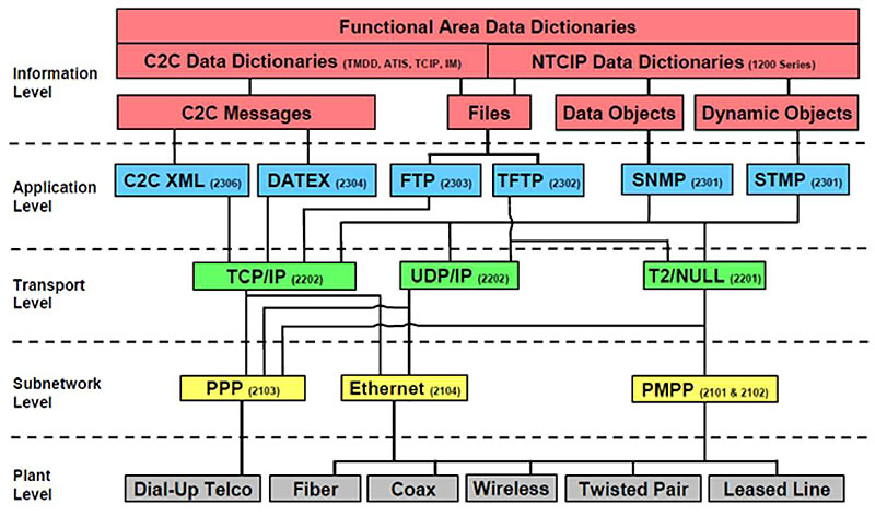
(Extended Text Description: Author's relevant notes: This slide contains a diagram depicting the structure of the NTCIP family of standards. The structure consists of five levels, from top to bottom: the Information Level, The Application Level, the Transport Level, The Subnetwork Level, and the Plant Level. The name of each level appears to the left side of the level, and the levels are separated by a dashed line. Each level contains a series of colored boxes. The Information level consists of three layers of red boxes. The top most box of the Information Level spans the width of the level, and is entitled "Functional Area Data Dictionaries." Adjacent to and below this box are two boxes, which are adjacent to each other and each take half the width of the level. The left most box is entitled "C2C Data Dictionaries (TMDD, ATIS, TCIP, IM)". The right most box is entitled "NTCIP Data Dictionaries (1200 Series)." The "C2C Data Dictionaries" box has a line leading to a box below it entitled "C2C Message" and a line to the right of that line leading to a box below it entitled "Files." The "NTCIP Data Dictionaries" also has a line leading to the "Files" box, as well as a line to the right of that leading to a box below it entitled "Data Objects," and a line to the right of that leading to a box below it entitled "Dynamic Objects." The Application Level consists of 6 blue boxes, which from left to right are entitled "C2C XML (2306)," "DATEX (2304)," "FTP (2303)," "TFTP (2302)," "SNMP (2301)," and "STMP (2301)." Connections from the Information Level to the Application Level are as follows: "C2C Messages" to "C2C XML" and "DATEX," "Files" to "FTP" and "TFTP," "Data Objects" to "SNMP," and "Dynamic Objects" to "STMP." The Transport Level consists of 3 green boxes, which from left to right are entitled "TCP/IP (2202)," "UDP/IP (2202)," and "T2/Null (2201)." Connections from the Application Level to the Transport Level are as follows: All boxes except "TFTP" lead to "TCP/IP," and the "TFTP," "SNMP," and "STMP" boxes all lead to the "UDP/IP" and "T2/Null" boxes. The Subnetwork level consist of three yellow boxes, which from left to right are entitled "PPP (2013)," "Ethernet (2014)," and "PMPP (2101 & 2012)." Connections to form the Transport Level to the Subnetwork Level are as follows: "TCP/IP" and "UDP/IP" to "PPP" and "Ethernet" and "T2/Null" to "PPP" and "PMPP." The Plant Level consists of six gray boxes, which from left to right are entitled "Dial-Up Telco," "Fiber," "Coax," "Wireless," "Twisted Pair," and "Leased Line." Connections from the Subnetwork Level are as follows: "PPP" to "Dial-Up Telco" and "Ethernet" and "PMPP" to "Fiber," "Coax," "Wireless," "Twisted Pair," and "Leased Line.")
Slide 16:
Learning Objective #1
Components and Structure of NTCIP 1211
What Is NTCIP 1211?
-
A communications interface, information-level standard for SCP systems
- Between a management station and a Priority Request Server (PRS);
- Between a management station and a Coordinator (CO);
- Between a Priority Request Generator (PRG) and a PRS; and
- Between a PRS and a CO.
Slide 17:
Learning Objective #1
Components and Structure of NTCIP 1211
History of NTCIP 1211
- Version 01: Published May 2008
-
Version 02:
- Published September 2014
-
Added the systems engineering process
- Defines the user needs supported by the standard
- Based on those user needs, defines the functional requirements supported by the standard
- Based on those functional requirements, defines a single design for each requirement
- Fixed a time reference problem
- Corrected errors and clarified ambiguities in NTCIP 1211 v01
Slide 18:
Learning Objective #1
Components and Structure of NTCIP 1211
Structure of the Standard
- Section 1: General
- Section 2: Concept of Operations
- Section 3: Functional Requirements
- Section 4: Dialogs
- Section 5: Management Information Base (MIB)
Slide 19:
Learning Objective #1
Components and Structure of NTCIP 1211
Structure of the Standard
- Annex A: Requirements Traceability Matrix (RTM)
- Annex B: Object Tree
- Annex C: Test Procedures
- Annex D: Documentation of Revisions
- Annex E: User Requests
- Annex F: SCP Tutorial
- Annex G: SNMP Interface
- Annex H: NTCIP 1201 v03 Derived User Needs, Functional Requirements, and Dialogs
Slide 20:
Learning Objective #1
Use a Protocol Requirements List (PRL) to Identify Requirements Desired or Supported
Protocol Requirements List
- A table in NTCIP that maps user needs to requirements
-
Can be used to:
- Specify the standard
- Assist deployments by providing a checklist
- Serve as the basis of selecting test procedures
-
Identify capabilities supported by an implementation
- For example, a vendor can complete a PRL to describe its product
- An agency can archive with project documentation
- Compare two implementations for interoperability
Slide 21:
Learning Objective #1
Use a Protocol Requirements List (PRL) to Identify Requirements Desired or Supported
Protocol Requirements List
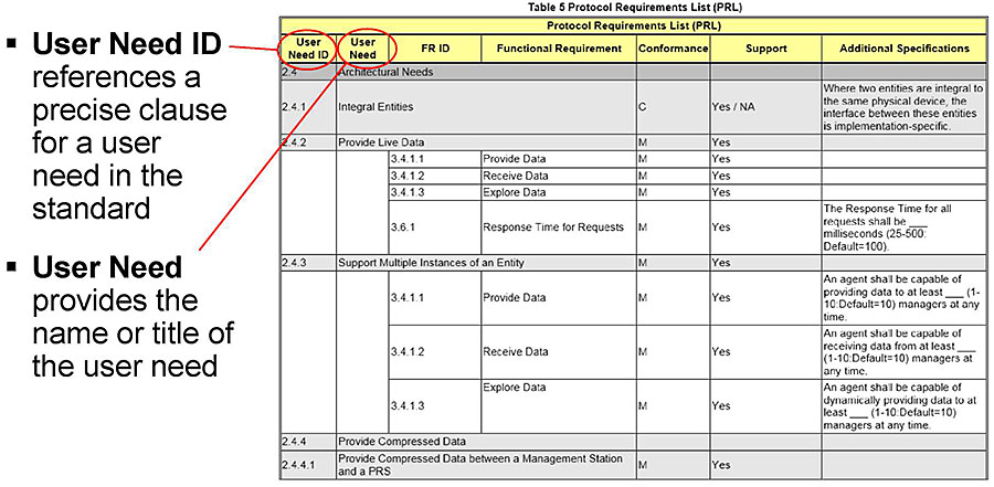
(Extended Text Description: This slide contains a table (see below for table content). There is a red circle around the text "User Need ID" in the header row of the table, with a line leading to a caption to the left of the table which reads "User Need ID references a precise clause for a user need in the standard." There is a red circle around the text "User Need" in the header row of the table with a line leading to a caption to the left of the table reading "User Need provides the name or title of the user need."
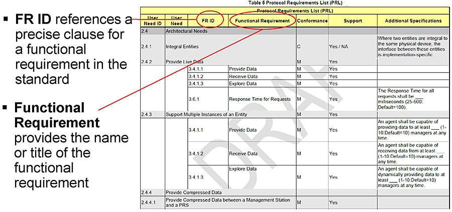
| Protocol Requirements List (PRL) | ||||||
| User Need ID | User Need | FR ID | Functional Requirement | Conformance | Support | Additional Specifications |
|---|---|---|---|---|---|---|
| 2.4 | Architectural Needs | |||||
| 2.4.1 | Integral Entities | C | Yes / NA | Where two entities are integral to the same physical device, the interface between these entities is implementation-specific. | ||
| 2.4.2 | Provide Live Data | M | Yes | |||
| 3.4.1.1 | Provide Data | M | Yes | |||
| 3.4.1.2 | Receive Data | M | Yes | |||
| 3.4.1.3 | Explore Data | M | Yes | |||
| 3.6.1 | Response Time far Requests | M | Yes | The Response Time for all requests shall be___ milliseconds (25-500: Default=100). | ||
| 2.4.3 | Support Multiple Instances of an Entity | M | Yes | |||
| 3.4.1.1 | Provide Data | M | Yes | An agent shall be capable of providing data to at least___(1- 10:Default=10) managers at any time. | ||
| 3.4.1.2 | Receive Data | M | Yes | An agent shall be capable of receiving data from at least___ (1-10:Default=10) managers at any time. | ||
| 3.4.1.3 | Explore Data | M | Yes | An agent shall be capable of dynamically providing data to at least___(1-10: Defaults 10) managers at any time. | ||
| 2.4.4 | Provide Compressed Data | |||||
| 2.4.4.1 | Provide Compressed Data between a Management Station and a PRS | M | Yes | |||
Slide 22:
Learning Objective #1
Use a Protocol Requirements List (PRL) to Identify Requirements Desired or Supported
Protocol Requirements List
(Extended Text Description: This slide contains the following text:
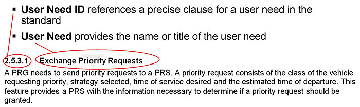
- User Need ID references a precise clause for a user need in the standard
- User Need provides the name or title of the user need
2.5.3.1 Exchange Priority Requests
A PRG needs to send priority requests to a PRS. A priority request consists of the class of the vehicle requesting priority, strategy selected, time of service desired and the estimated time of departure. This feature provides a PRS with the information necessary to determine if a priority request should be granted.
Note: There is a red circle around the text "2.5.3.1" with a line leading to a caption that reads "User Need ID references a precise clause for a user need in the standard." There is a red circle around the text "Exchange Priority Requests" with a line leading to a caption that reads "User Need provides the name or title of the user need.")
Slide 23:
Learning Objective #1
Use a Protocol Requirements List (PRL) to Identify Requirements Desired or Supported
Protocol Requirements List
- User needs describe what features a component needs to support and why
- Functional requirements refine the user needs into detailed, measurable specifications
-
Within the PRL, the relationships between user needs and functional requirements are standardized
- User needs justify and explain requirements
- Requirements refine needs to measureable concepts
- Promotes interoperability
Slide 24:
Learning Objective #1
Use a Protocol Requirements List (PRL) to Identify Requirements Desired or Supported
Protocol Requirements List
(Extended Text Description: This slide contains the same table as Slide 21. There is a red circle around the text "FR ID" in the header row with a line leading to a caption that reads "FR ID references a precise clause for a functional requirement in the standard." There is a red circle around "Functional Requirement" in the header row with a line leading to a caption that reads "Functional Requirement provides the name or title of the functional requirement.")
Slide 25:
Learning Objective #1
Use a Protocol Requirements List (PRL) to Identify Requirements Desired or Supported
Protocol Requirements List
(Extended Text Description: This slide contains the following text:
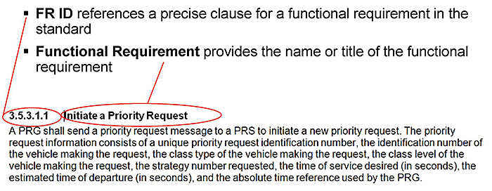
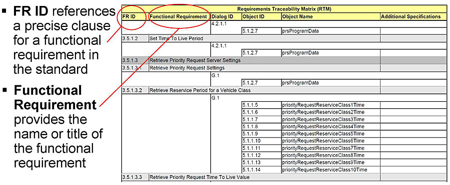
- FR ID references a precise clause for a functional requirement in the standard
- Functional Requirement provides the name or title of the functional requirement
3.5.3.1.1 Initiate a Priority Request
A PRG shall send a priority request message to a PRS to initiate a new priority request. The priority request information consists of a unique priority request identification number, the identification number of the vehicle making the request, the class type of the vehicle making the request, the class level of the vehicle making the request, the strategy number requested, the time of service desired (in seconds), the estimated time of departure (in seconds), and the absolute time reference used by the PRG.
Note: There is a red circle around the text "3.5.3.1.1" in the header line with a line leading to a caption that reads "FR ID references a precise clause for a functional requirement in the standard." There is a red circle around the text "Initiate a Priority Request" in the header line with a line leading to a caption that reads "Functional Requirement provides the name or title of the functional requirement.")
Slide 26:

Slide 27:
Learning Objective #1
What can the PRL NOT be used for?
Answer Choices
- Specify the standard
- Map user needs to requirements
- Identify the user needs supported by the standard
- Identify the most qualified vendor
Slide 28:
Learning Objective #1
Review of Answers
 a) Specify the standard
Incorrect. The PRL can be used to specify the standard for an implementation.
b) Map user needs to requirements
Incorrect. The PRL maps user needs to requirements.
c) Identify the user needs supported by the standard
Incorrect. The PRL includes the user needs supported by the standard.
 d) Identify the most qualified vendor
Correct! The PRL can identify if a vendor supports a user need, but not its qualifications.
Slide 29:
Learning Objective #1
Describe the Organization and Decomposition of Requirements of the NTCIP 1211 Standard
Requirements
-
NTCIP 1211 contains three types of requirements:
- Architectural Requirements
- Data Exchange and Operational Environmental Requirements
- Supplemental Non-Communications Requirements
Slide 30:
Learning Objective #1
Describe the Organization and Decomposition of Requirements of the NTCIP 1211 Standard
Well-Formed Requirements
[Actor] [Action] [Target] [Constraint] [Localization]
- Actor - Identifies who or what that does the action
- Action - Identifies what is to happen
- Target - Identifies who or what receives the action
3.5.3.1.1 Initiate a Priority Request
A PRG shall send a priority request message to a PRS to initiate a new priority request. The priority request information consists of a unique priority request identification number, the identification number of the vehicle making the request, the class type of the vehicle making the request, the class level of the vehicle making the request, the strategy number requested, the time of service desired (in seconds), the estimated time of departure (in seconds), and the absolute time reference used by the PRG.
Slide 31:
Learning Objective #1
Describe the Organization and Decomposition of Requirements of the NTCIP 1211 Standard
Well-Formed Requirements
[Actor] [Action] [Target] [Constraint] [Localization]
-
Optional
- Constraint - Identifies how to measure success or failure of the requirement
-
Localization - Identifies the circumstances under which the requirement applies.
- For example, upon request, the management station shall retrieve from the CO the default coordination pattern to be used
Slide 32:
Learning Objective #1
Describe the Organization and Decomposition of Requirements of the NTCIP 1211 Standard
Architectural Requirements
-
Architectural requirements support communications from multiple entities:
- Provide Data
- Receive Data
- Explore Data
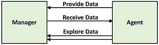
(Extended Text Description: This slide contains a graphic showing a data exchange architecture. On the left is a green square box entitled "Manager" and on the right is a green square box entitled "Agent." Between the boxes is a series of lines with arrowheads on one end, leading from one box to the other. The topmost line moves from the "Agent" box to the "Manager" box and reads "Provide Data." The next line moves from the "Manager" box to the "Agent" box and reads "Receive Data." The final two lines move from the "Agent" box to the "Manager box," and read "Explore Data.")
Slide 33:
Learning Objective #1
Describe the Organization and Decomposition of Requirements of the NTCIP 1211 Standard
Data Exchange and Operational Environmental Requirements
-
PRG to PRS
-
Retrieve Priority Requests
-
Initiate a Priority Request
- Priority Request Identifier
- Vehicle Identifier
- Vehicle Class Type (1-10)
- Vehicle Class Level (1-10)
- Service Strategy Number
- Time of Service
- Time of Estimated Departure
- Time of Request
-
Initiate a Priority Request
-
Retrieve Priority Requests
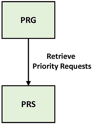
(Extended Text Description: This slide contains a graphic showing a data exchange architecture. There is a green box on top which is entitled "PRG" and a green box on the bottom entitled "PRS." A line with an arrowhead flows from the top box to the bottom box and reads "Retrieve Priority Requests.")
Slide 34:
Learning Objective #1
Describe the Organization and Decomposition of Requirements of the NTCIP 1211 Standard
Data Exchange and Operational Environmental Requirements Interface
-
PRG to PRS
-
Retrieve Priority Requests (Continued)
- Send a Priority Request Update
- Send a Cancel Priority Request Update
- Send a Clear Priority Request
- Initiate a Priority Request - NTCIP 1211 v01. Did not include time of request.
- Send a Priority Request Update - NTCIP 1211 v01
- Receive a Priority Request Status
-
Retrieve Priority Requests (Continued)
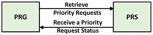
(Extended Text Description: This slide contains a graphic showing a data exchange architecture. There is a green box on the left entitled "PRG" and a green box on the right entitled "PRS". There is a line with an arrowhead leading from the "PRG" box to the "PRS" box that reads "Retrieve Priority Requests." Below that, there is a line with an arrowhead leading from the "PRS" box to the "PRG" box that reads "Receive a Priority Request Status.")
Slide 35:
Learning Objective #1
Describe the Organization and Decomposition of Requirements of the NTCIP 1211 Standard
Data Exchange and Operational Environmental Requirements Interface
-
PRS to CO
- Exchange Service Request
- Exchange Service Request Status
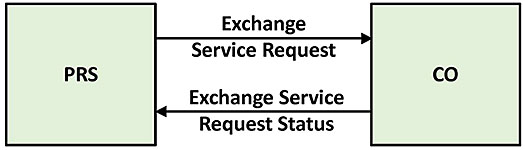
(Extended Text Description: This slide contains a graphic showing a data exchange architecture. On the left there is a green box entitled "PRS" and on the right there is a green box entitled "CO." There is a line with an arrowhead leading from the "PRS" box to the "CO" box that reads "Exchange Service Request." There is a line with an arrowhead leading from the "CO" box to the "PRS" box that reads "Exchange Service Request Status.")
Slide 36:
Learning Objective #1
Describe the Organization and Decomposition of Requirements of the NTCIP 1211 Standard
Data Exchange and Operational Environmental Requirements Interface
-
Management Station to PRS
- Set Reservice Period
- Set Time to Live Period
-
Retrieve Priority Request Server Settings
- Retrieve Priority Request Settings
- Retrieve Reservice Period for Vehicle Class
- Retrieve Priority Request Time to Live Value
- Monitor the Status of the PRS
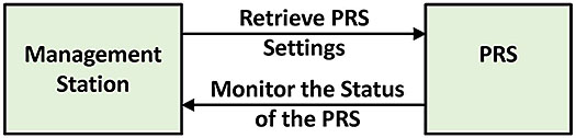
(Extended Text Description: This slide contains a graphic showing a data exchange architecture. On the left is a green box entitled "Management Station." On the right is a green box entitled "PRS." There is a line with an arrowhead leading from the "Management Station" box to the "PRS" box that reads "Set Period." Below that, there is a line with an arrowhead leading from the "Management Station" box to the "PRS" box that reads "Retrieve PRS Settings." Below that, there is a line with an arrowhead leading from the "PRS" box to the "Management Station" box that reads "Monitor the Status of the PRS.")
Slide 37:
Learning Objective #1
Describe the Organization and Decomposition of Requirements of the NTCIP 1211 Standard
Data Exchange and Operational Environmental Requirements Interface
-
Management Station to CO
-
Configure the CO
- Set Priority Strategy Configuration
- Define Default Coordination Pattern
- Define Maximum Priority Strategies Supported
- Define Maximum Service Requests to Consider
-
Configure the CO
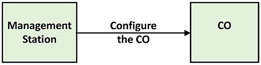
(Extended Text Description: This slide contains a graphic showing a data exchange architecture. On the left is a green box entitled "Management Station." On the right is a green box entitled "CO." There is a line with an arrowhead leading from the "Management Station" box to the "CO" box that reads "Configure the CO.")
Slide 38:
Learning Objective #1
Describe the Organization and Decomposition of Requirements of the NTCIP 1211 Standard
Data Exchange and Operational Environmental Requirements Interface
-
Management Station to CO (Continued)
-
Retrieve Priority Strategy Configuration
- Retrieve Priority Strategy Settings
- Retrieve Priority Strategies
- Retrieve Priority Splits
- Retrieve Default Coordination Pattern
- Retrieve Maximum Priority Strategies Supported
- Retrieve Maximum Service Requests to Consider
- Monitor the Status of the CO
-
Retrieve Priority Strategy Configuration
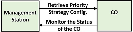
(Extended Text Description: This slide contains a graphic showing a data exchange architecture. On the left there is a green box entitled "Management Station." On the right is a green box entitled "CO." There is a line with an arrowhead leading from the "Management Station' box to the "CO" box that reads "Retrieve Priority Strategy Config." Below that line there is a line with an arrowhead leading from the "CO" box to the "Management Station" box that reads "Monitor the Status of the CO.")
Slide 39:
Learning Objective #1
Describe the Organization and Decomposition of Requirements of the NTCIP 1211 Standard
Supplemental Non-Communications Requirements
- Response Time for Requests
-
Process Priority Requests
- Support Multiple Priority Requests
- Clear Expired Priority Requests
- Support Multiple Priority Requests - NTCIP 1211 v01
- Process Service Requests
Slide 40:
Summary of Learning Objective #1
Describe Requirements Included in the NTCIP 1211 Standard
- NTCIP is a family of standards; NTCIP 1211 is a communications interface standard for signal control priority systems
- NTCIP 1211 v02 incorporates a systems engineering process
- The Protocol Requirements List (PRL) is a table that maps user needs to requirements
- Besides general architectural requirements, NTCIP 1211 v02 organizes functional requirements by interface
Slide 41:
Learning Objective #2: Use the Protocol Requirements List (PRL) to Specify Requirements
- Select the user needs and link to requirements
- Explain the use of optional requirements and constraints within the PRL
- Specify performance criteria for functional requirements within the PRL
- Specify limits or ranges for functional requirements within the PRL
- Use the PRL in a project specification for transit signal priority
Slide 42:
Learning Objective #2
Select the User Needs and Link to Requirements
PRL - Conformance
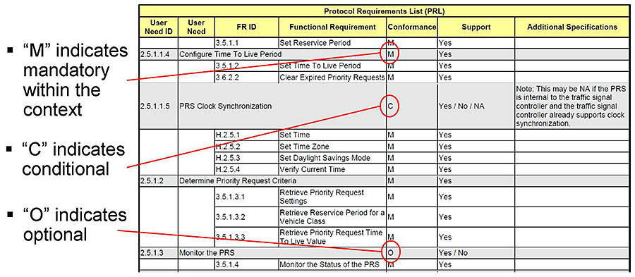
(Extended Text Description: This slide contains a table:
| Protocol Requirements List (PRL) | ||||||
| User Need ID | User Need | FR ID | Functional Requirement | Conformance | Support | Additional Specifications |
|---|---|---|---|---|---|---|
| 3.5.1.1 | Set Reservice Period | M | Yes | |||
| 2.5.1.1.4 | Configure Time To Live Period | M | Yes | |||
| 3.5.1.2 | Set Time To Live Period | M | Yes | |||
| 3.6.2.2 | Clear Expired Priority Requests | M | Yes | |||
| 2.5.1.1.5 | PRS Clock Synchronization | C | Yes/No / NA | Note: This may be NA if the PRS is internal to the traffic signal controller and the traffic signal controller already supports clock synchronization. | ||
| H.2.5.1 | Set Time | M | Yes | |||
| H.2.5.2 | Set Time Zone | M | Yes | |||
| H.2.5.3 | Set Daylight Savings Mode | M | Yes | |||
| H.2.5.4 | Verify Current Time | M | Yes | |||
| 2.5.1.2 | Determine Priority Request Criteria | M | Yes | |||
| 3.5.1.3.1 | Retrieve Priority Request Settings | M | Yes | |||
| 3.5.1.3.2 | Retrieve Reservice Period for a Vehicle Class | M | Yes | |||
| 3.5.1.3.3 | Retrieve Priority Request Time To Live Value | M | Yes | |||
| 2.5.1.3 | Monitor the PRS | 0 | Yes/No | |||
| 3.5.1.4 | Monitor the Status of the PRS | M | Yes | |||
In the fourth row of the table, "M" in column 5 is circled in red, with a line leading to a caption at the left of the table reading "'M' indicates mandatory within the context." In the seventh row of the table, "C" in column 5 is circled in red, with a line leading to a caption at the left of the table reading "'C' indicates conditional." In the sixteenth row of the table, "O" is column 5 is circled in red with a line leading to a caption at the left of the table reading "'O' indicates optional.")
Slide 43:
Learning Objective #2
Select the User Needs and Link to Requirements PRL - Support
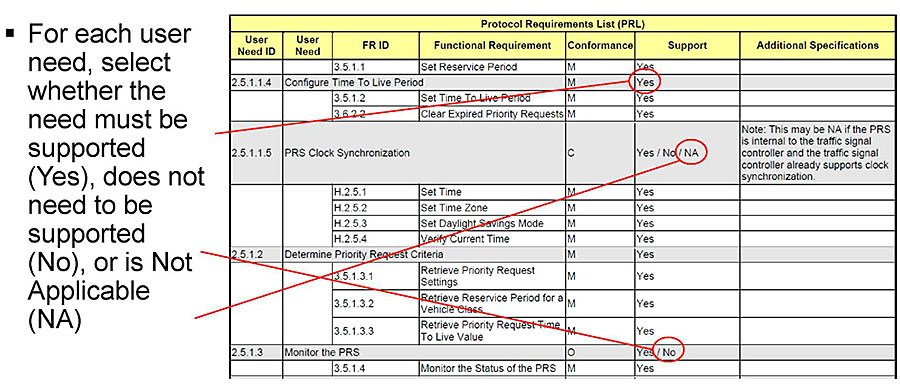
(Extended Text Description: This slide contains the same table as Slide 42. To the left of the table is a caption that reads "For each user need select if the user need is to be supported (Yes), does not need to be supported (No) or Not applicable (NA). In the fourth row of the table, "Yes" in column 6 is circled in red, with a line leading to the caption at the left. In the seventh row of the table, "NA" in column 6 is circled in red, with a line leading to the caption at the left. In the sixteenth row of the table, "No" in column 6 is circled in red, with a line leading to the caption at the left.)
Slide 44:
Learning Objective #2
Explain the Use of Optional Requirements and Constraints within the PRL
PRL -Associated Requirements
(Extended Text Description: This slide contains a table:
| Protocol Requirements List (PRL) | ||||||
| User Need ID | User Need | FR ID | Functional Requirement | Conformance | Support | Additional Specifications |
|---|---|---|---|---|---|---|
| 2.5.5.1 | Backward Compatible with NTCIP 1211 v01 | O | Yes/No | Note: These object definitions have not been deprecated to address interoperability issues with NTCIP 1211 v01. The associated objects were deprecated and replaced by newer objects that have a wider scope or that have been changed to ease implementation. Pay close attention to the implementation and interoperability of these objects. | ||
| 3.5.3.1.5 | Initiate a Priority Request -NTCIP 1211 v01 | C | Yes/NA | If the PRG and PRS are integral to the same physical device, the interface between these entities is implementation-specific. | ||
| 3.5.3.1.6 | Send a Priority Request Update-NTCIP 1211 v01 | C | Yes/NA | If the PRS and CO are integral to the same physical device, the interface between these entities is implementation-specific. | ||
| 3.6.2.3 | Support Multiple Priority Requests - NTCIP 1211 v01 | M | Yes | The PRS shall be capable of supporting at least_(1 - 10:Default=10) and no more than (1-10:Default=10) priority requests. | ||
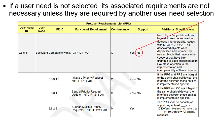
The table ends after this row. In the third row, there is a red circle around "No" in column 6, with a line leading to a caption that reads "If a user need is not selected, its associated requirements are not necessary unless they are required by another user need selection.")
Slide 45:
Learning Objective #2
Explain the Use of Optional Requirements and Constraints within the PRL
PRL - Associated Requirements
- If a user need is selected, for each requirement indicate whether the requirement is to be supported (Yes), does not need to be supported (No), or is Not Applicable (NA)
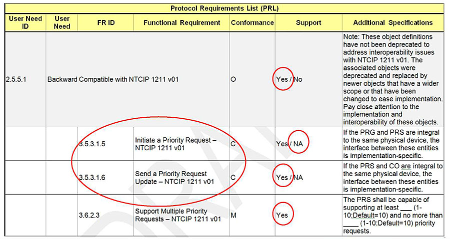
(Extended Text Description: This slide contains the same table as Slide 44. There is a large round circle over a portion of the table, which appears to encircle columns 3, 4, and 5 of the fourth and fifth rows of the table. There are red circles over the following: "Yes" in column 6 of the third, fifth, and sixth rows, and "NA" in column 6 of the fourth row.)
Slide 46:
Learning Objective #2
Specify Performance Criteria for Functional Requirements within the PRL
Protocol Requirements List -Additional Specifications
(Extended Text Description: This slide contains a table:
| Protocol Requirements List (PRL) | ||||||
| User Need ID | User Need | FR ID | Functional Requirement | Conformance | Support | Additional Specifications |
|---|---|---|---|---|---|---|
| 2.4 | Architectural Needs | |||||
| 2.4.1 | Integral Entities | C | Yes / NA | Where two entities are integral to the same physical device, the interface between these entities is implementation-specific. | ||
| 2.4.2 | Provide Live Data | M | Yes | |||
| 3.4.1.1 | Provide Data | M | Yes | |||
| 3.4.1.2 | Receive Data | M | Yes | |||
| 3.4.1.3 | Explore Data | M | Yes | |||
| 3.6.1 | Response Time for Requests | M | Yes | The Response Time for all requests shall be_ milliseconds (25-500: Default=100). | ||
There is a red circle around column 7 of the last row.)
-
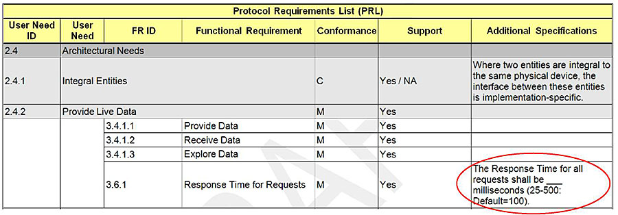
Used to enter additional notes and requirements
- For example, defining performance criteria or to specify limits or ranges for functional requirements
- Used to provide further details about an implementation
Slide 47:
Learning Objective #2
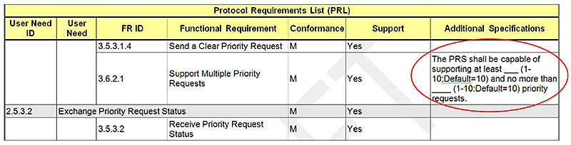
Specify Limits or Ranges for Functional Requirements within the PRL
Protocol Requirements List -Additional Specifications
(Extended Text Description: This slide contains a table:
| Protocol Requirements List (PRL) | ||||||
| User Need ID | User Need | FR ID | Functional Requirement | Conformance | Support | Additional Specifications |
|---|---|---|---|---|---|---|
| 3.5.3.1.4 | Send a Clear Priority Request | M | Yes | |||
| 3.6.2.1 | Support Multiple Priority Requests | M | Yes | The PRS shall be capable of supporting at least ____ (1-10:Default=10) and no more than ____ (1-10:Default=10) priority requests. | ||
| 2.5.3.2 | Exchange Priority Request Status | M | Yes | |||
| 3.5.3.2 | Receive Priority Request Status | M | Yes | |||
In the fourth row, column 7 is circled in red.)
Slide 48:
Learning Objective #2
Use the PRL in an SCP Specification
Part of the Interface Specification
- A transit agency's completed PRL specifies the needs and requirements for the NTCIP interface
- When combined with the communication specification, it forms an interface specification
-
A vendor may "exceed the specification"
- Support features not selected
- Allows vendors to bid on more projects with a single model
-
A deployment may need multiple interface specifications
- Management systems that support multiple devices
- May need support for legacy protocol
Slide 49:
Learning Objective #2
Use the PRL in an SCP Specification
Consistency
- The interface specification must be consistent with the remainder of the specification
-
Management Station - PRS and Management Station - CO interfaces have requirements to set the time
- Implies existence of clocks in the PRS and the CO
- Requires software logic to update the clock
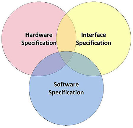
(Extended Text Description: This slide contains three partially overlapping circles. There is a pink circle entitled "Hardware Specifications." There is a yellow circle to the right of the pink circle that overlaps with the pink circle slightly entitled "Interface Specification." There is a blue circle at the center below the pink and yellow circles, overlapping slightly with both circles entitled "Software Specification.")
Slide 50:
Learning Objective #2
Use the PRL in an SCP Specification
Sample Text for using the PRL in a Specification
- The PRL should be properly introduced within the specification
- Copyright disclaimer should appear with the PRL
Slide 51:

Slide 52:
Learning Objective #2
Which of the following elements is NOT a purpose of the PRL?
Answer Choices
- Associate user needs with requirements
- Specify the requirements for a specific project
- Determine which objects to use
- Determine the minimum requirements for conformance
Slide 53:
Learning Objective #2
Review of Answers
a) Associate user needs with requirements
Incorrect. This is one of the key purposes of the PRL.
b) Specify the requirements for a specific project
Incorrect. The PRL allows the agency to specify the user needs and requirements for a project.
c) Determine which objects to use
Correct! The PRL does not help determine which objects to use for an implementation.
d) Determine the minimum requirements for conformance
Incorrect. The PRL indicates what user needs and requirements are mandatory to conform to the standard.
Slide 54:
Summary of Learning Objective # 2
Use the Protocol Requirements List (PRL) to Specify Requirements
A PRL is a tool in the standard to:
- Select user needs and requirements for a project implementation;
- Specify performance criteria and ranges for requirements; and
- Determine the capabilities of an implementation.
Slide 55:
Learning Objective #3: Show How to Achieve Interoperability and Interchangeability Using the Requirements Traceability Matrix (RTM)
- Explain how the RTM traces to a single design
- Demonstrate how to compare for interoperability
Slide 56:
Learning Objective #3
Explain How the RTM Traces to a Single Design
Interoperability
- Ability of different components, or for the purpose of this module, transit signal priority components from different vendors, to exchange information and to use the information that has been exchanged
-
Interoperability is a key objective for using the standards
- Interoperability reduces risks and, by extension, costs
-
Interchangeability
- Ability of one component to be used in place of or be replaced by another component
Slide 57:
Learning Objective #3
Explain How the RTM Traces to a Single Design
Annex A Contains a Requirements Traceability Matrix
-
Describes the (standard) design for fulfilling a requirement
- Requirements can be traced in a standardized way
- Reduces design work
- Design consists of a dialog (sequence of data exchanges) and object(s) to be exchanged
- To conform to a requirement, a transit signal priority (TSP) system must support the standardized dialogs and objects specified in NTCIP 1211 v02, with the expected result
- Results in interoperability - all systems shall satisfy a specified requirement the same way
Slide 58:
Learning Objective #3
Explain How the RTM Traces to a Single Design
Requirements Traceability Matrix
(Extended Text Description: This slide contains a table:
| Requirements Traceability Matrix (RTM) | |||||
| FR ID | Functional Requirement | Dialog ID | Object ID | Object Name | Additional Specifications |
|---|---|---|---|---|---|
| 4.2.1.1 | |||||
| 5.1.2.7 | prsProgramData | ||||
| 3.5.1.2 | Set Time To Live Period | ||||
| 4.2.1.1 | |||||
| 5.1.2.7 | prsProgramData | ||||
| 3.5.1.3 | Retrieve Priority Request Server Settings | ||||
| 3.5.1.3.1 | Retrieve Priority Request Settings | ||||
| G.1 | |||||
| 5.1.2.7 | prsProgramData | ||||
| 3.5.1.3.2 | Retrieve Reservice Period for a Vehicle Class | ||||
| G.1 | |||||
| 5.1.1.5 | priorityRequestReserviceClass1Time | ||||
| 5.1.1.6 | priorityRequestReserviceClass2Time | ||||
| 5.1.1.7 | priorityRequestReserviceClass3Time | ||||
| 5.1.1.8 | priorityRequestReserviceClass4Time | ||||
| 5.1.1.9 | priorityRequestReserviceClass5Time | ||||
| 5.1.1.10 | priorityRequestReserviceClass6Time | ||||
| 5.1.1.11 | priorityRequestReserviceClass7Time | ||||
| 5.1.1.12 | priorityRequestReserviceClass8Time | ||||
| 5.1.1.13 | priorityRequestReserviceClass9Time | ||||
| 5.1.1.14 | priorityRequestReserviceClass10Time | ||||
| 3.5.1.3.3 | Retrieve Priority Request Time To Live Value | ||||
In the second row, "FR ID" in column 1 is circled in red, with a line leading to a caption that reads "FR ID references a precise clause for a functional requirement in the standard". In the second row, "Functional Requirement" in column 2 is circled in red with a line leading to a caption that reads "Function Requirement provides the name or title of the functional requirement.")
Slide 59:
Learning Objective #3
Explain How the RTM Traces to a Single Design
Requirements Traceability Matrix
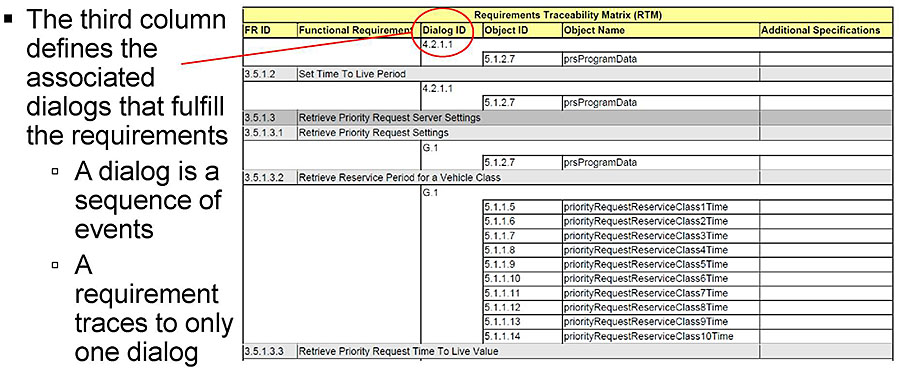
(Extended Text Description: This slide contains the same table as Slide 58. In the second row, "Dialog ID" in column 3 is circled in red with a line leading to a caption that reads "The third column defines the associated dialogs that fulfill the requirements. A dialog is a sequence of events. A requirement traces to only one dialog.")
Slide 60:
Learning Objective #3
Explain How the RTM Traces to a Single Design
Requirements Traceability Matrix
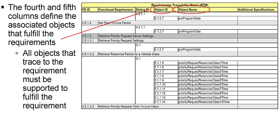
(Extended Text Description: This slide contains the same table as Slide 58. In the second row, "Object ID" in column 4 and "Object Name" in column 5 are circled in red. A line leads from these circles to a caption that reads "The fourth and fifth columns define the associated objects that fulfill the requirements. All objects that trace to the requirement must be supported to fulfill the requirement.)
Slide 61:
Learning Objective #3
Explain How the RTM Traces to a Single Design
Requirements Traceability Matrix
(Extended Text Description: This slide contains a table:
| Requirements Traceability Matrix (RTM) | |||||
| FR ID | Functional Requirement | Dialog ID | Object ID | Object Name | Additional Specifications |
|---|---|---|---|---|---|
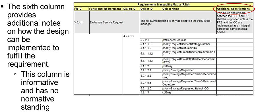
| 3.5.4.1 | Exchange Service Request | The following mapping is only applicable if the PRS is the manager. | This dialog and objects between the PRS and CO shall be supported unless the PRS and the CO are implemented as an integral part of the same physical device. | ||
| 4.2.4.1.2 | |||||
| 5.2.2.1 | prsServiceRequest | ||||
| 5.1.1.1.6 | priorityRequestServiceStrategyNumber | ||||
| 5.1.1.1.9 | priorityRequestStatusInPRS | ||||
| 5.1.1.1.12 | priorityRequestTimeOfServiceDesiredInPRS | ||||
| 5.1.1.1.13 | priorityRequestTimeOfEstimatedDepartureInPRS | ||||
| 5.1.1.2 | prsBusy | ||||
| 5.2.1.2.2 | priorityStrategyRequested | ||||
| 5.2.1.2.3 | priorityStrategyRequestedTimeOfServiceDesired | ||||
| 5.2.1.2.4 | priorityStrategyRequestedTimeOfEstimatedDeparture | ||||
| 5.2.1.2.5 | priorityStrategyRequestedStatusInCO | ||||
| 5.2.1.3 | coBusy | ||||
In the second row, "Additional Specifications" in column 6 is circled in red. A caption to the left of the table reads "The sixth column provides additional notes on how the design can be implemented to fulfill the requirement. This column is informative and have no normative standing.")
Slide 62:
Learning Objective #3
Demonstrate How to Compare for Interoperability
Compare PRLs for Interoperability
- RTM provides interoperability at individual requirement level
- PRL indicates which requirements are supported/required
- Comparisons of PRLs allow quick determination of interoperability
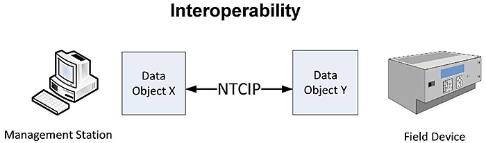
(Extended Text Description: This slide contains a graphic entitled "Interoperability." The left of the graphic contains an image of a computer, and a caption that reads "Management Station." To the right of the computer is a light blue square box entitled "Data Object X." To the right of that box is a square box entitled "Data Object Y." Between these two boxes is a line with an arrowhead on each end that reads "NTCIP." To the right of the "Data Object Y" box is an image of a field controller, with a caption below reading "Field Device.")
Slide 63:
Learning Objective #3
Demonstrate How to Compare for Interoperability
Compare PRLs for Interoperability
-
Both the manager and the agent support a requirement
- Interoperability provided for that requirement
-
The manager supports but the agent does not
- The manager can still support the requirement (typically)
- The manager can still interoperate with other agents that support the requirement
-
The agent supports, but the manager does not
- Feature could be used by other/future managers
- Feature can potentially be used manually
Slide 64:

Slide 65:
Learning Objective #3
Which of the following are not part of the RTM?
Answer Choices
- User needs supported by the standard
- Requirements supported by the standard
- Standardized dialogs to fulfill requirements
- Data objects to fulfill requirements
Slide 66:
Learning Objective #3
Review of Answers
a) User needs supported by the standard
Correct! User needs are not included in the RTM.
b) Requirements supported by the standard
Incorrect. Each requirement supported by the standard is listed in the RTM.
c) Standardized dialogs to fulfill requirements
Incorrect. Each requirement includes a standardized dialog to fulfill the requirement.
d) Data objects to fulfill requirements
Incorrect. Each requirement includes one or more data objects to fulfill the requirement.
Slide 67:
Summary of Learning Objective #3
Show How to Achieve Interoperability and Interchangeability Using the Requirements Traceability Matrix (RTM)
The Requirements Traceability Matrix:
- Maps each requirement to a specific design consisting of a dialog and data objects
- Supports interoperability and interchangeability
- The PRL allows for easy checks for interoperability
Slide 68:
Learning Objective #4: Explain the NTCIP 1211 SNMP Interface and Dialogs
- Describe a typical Simple Network Management Protocol (SNMP) dialog
- Describe an example of an NTCIP 1211 dialog
Slide 69:
Learning Objective #4
Describe a Typical SNMP Dialog
Dialogs
-
Standardized NTCIP dialogs
- GET request
- SET request
- GET-NEXT request
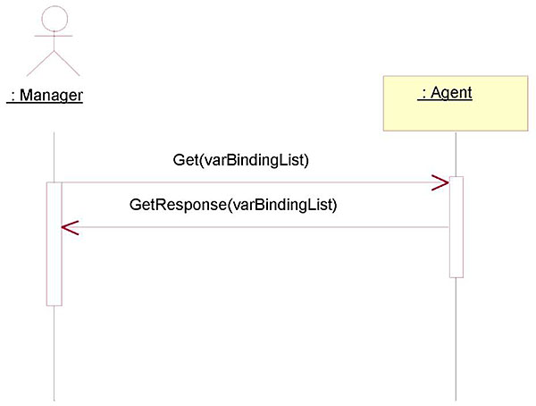
(Extended Text Description: This slide contains a graphic that depicts an SNMP dialog using UML. There is a stick-figure depiction of a person, with the caption "Manager" on the left side. There is a yellow horizontally oriented yellow rectangular box entitled "Agent' on the right side. Below both the "Manager" and the "Agent" representations on each side is a vertical line that leads to a vertically oriented rectangular box. The box on the left is longer than the box on the right. Below these rectangular boxes are another vertical line. At the top of the left vertical box that is below the "Manager" representation is a solid line with an arrow head leading to the top of the vertical box below the "Agent" representation, reading "Get(varBindingList)." At the center of the vertical box below the "Agent" representation is a dashed line with an arrowhead leading from to the vertical box below the "Manager" representation, reading "GetResponse(varBindingList).")
Slide 70:
Learning Objective #4
Describe an Example of an NTCIP 1211 Dialog
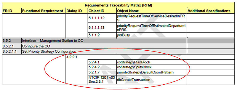
Dialogs
-
All objects referenced anywhere in dialog are shown in the RTM
- RTM provides traceability
- Dialog gives sequencing rules
(Extended Text Description: This slide contains a table:
| Requirements Traceability Matrix (RTM) | |||||
| FR ID | Functional Requirement | Dialog ID | Object ID | Object Name | Additional Specifications |
|---|---|---|---|---|---|
| 5.1.1.1.12 | priorityRequestTimeOfServiceDesiredInPRS | ||||
| 5.1.1.1.13 | priorityRequestTimeOfEstimatedDepartureInPRC | ||||
| 5.1.1.2 | prsBusy | ||||
| 3.5.2 | Interface - Management Station to CO | ||||
| 3.5.2.1 | Configure the CO | ||||
| 3.5.2.1.1 | Set Priority Strategy Configuration | ||||
| 4.2.2.1 | |||||
| 5.2.4.1 | coStrategyPlanBlock | ||||
| 5.2.4.2 | coStrategySplitBlock | ||||
| 5.2.1.7 | priorityStrategyDefaultCoordPattem | ||||
| NTCIP 1201 v03 Sec.2.3.1 | dbCreateTransaction | ||||
There is a red circle surrounding columns 3, 4, and 5 of the final five rows of the table.)
Slide 71:
Learning Objective #4
Describe an Example of an NTCIP 1211 Dialog
Example Dialog
4.2.2.1 Set the Priority Strategy Configuration
4.2.2.1.1 Standardized Dialog
The following is the standardized dialog for a management station to configure the priority strategy settings in a CO. The management station shall use dbCreateTransaction', as defined in NTCIP 1201 v03 Section 2.3.1, to SET this object. The CO shall NOT allow a normal SNMP SET The use case diagram for 'dbCreateTransaction' is depicted in Figure 8.
The standardized dialog to configure the priority strategy settings in a CO is:
- The traffic signal controller shall be in transaction mode (See Section 4.2.2.1.3).
- The management station shall SET coStrategyPlanBlock x
- The management station shall SET coStrategySplitsBlock.x.
- The management station shall SET priohtyStrategyDefaultCoordPattern.
- The consistency checks to be performed on downloaded data when the "verily" state is commanded is defined in Section 4.2.2 1.2.
- The controller shall exit transaction mode.
Slide 72:
Learning Objective #4
Describe an Example of an NTCIP 1211 Dialog
Sequence of Events in a Dialog
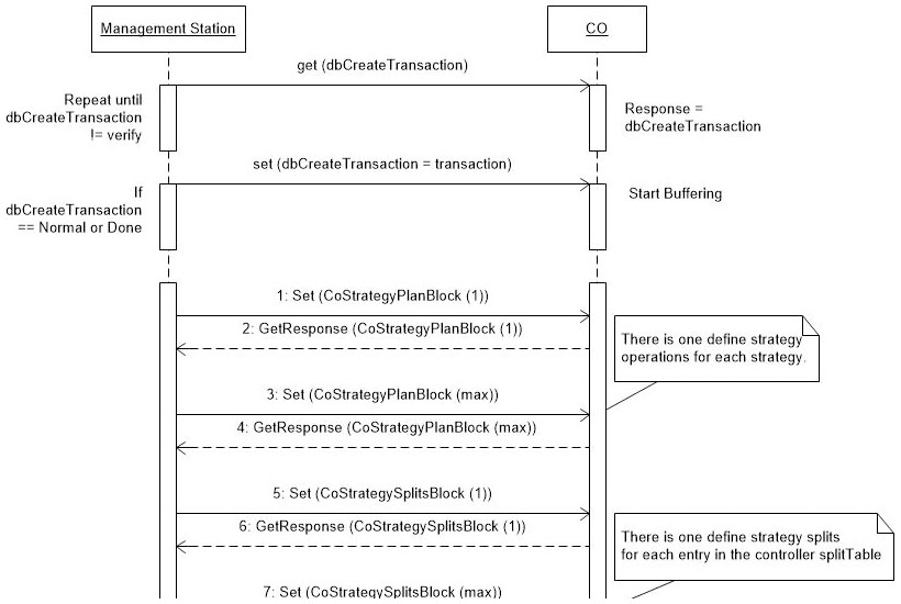
(Extended Text Description: The slide contains a UML diagram. At the top, there is a horizontally oriented box entitled "Management Station" on the left and a horizontally oriented box entitled "CO" on the right. Both of these boxes have a vertical dashed line that leads downward to a vertically oriented box on respective sides of the graphic. At this level of the graphic, there is a caption to the left of the left vertical box that reads "Repeat until dbCreateTransaction != verify." To the right of the right vertical box is a caption that reads "Response = dbCreateTransaction." At the top of the left vertical box is a solid line with an arrowhead on the end leading to the top of the right vertical box, with a caption over the line reading get(dbCreateTransaction). Both the left and vertical boxes have a vertical dashed line leading downward to another vertical box on respective sides. To the left of the left vertical box is a caption that reads "If dbCreateTransaction == Normal or done." To the right of the right vertical box is a caption that reads "Start Buffering." At the top of the left vertical box is a solid line with an arrowhead leading to the top of the right vertical box. There is a caption over the line reading "set (dbCreateTransaction = transaction)." Both the left and right vertical box have a vertical dashed line that leads to a long vertical box on both respective sides, which is open at the bottom. Between the two vertical boxes are a series of lines with arrowheads on one end. The topmost line is solid and leads left to right, with a caption that reads "1: Set (CoStrategyPlanBlock (1))." The next line is dashed and leads right to left, with a caption that reads "2: GetResponse (CoStrategyPlanBlock (1))." The next line is solid and leads left to right, with a caption that says "3: Set (CoStrategyPlanBlock (max))." There is another caption box to the right with a line leading to this line that reads "There is one define strategy operations for each strategy." The next line is a dashed and leads right to left with a caption that reads "4: GetResponse (CoStrategyPlanBlock (max))." The next line is solid and leads left to right with a caption that reads "5: Set (CoStrategySplitsBlock (1))." The next line is dashed and leads right to left with a caption that reads "6: GetResponse (CoStrategySplitsBlock (1))." Below that line is another caption, with no visible associated line that reads "7: Set (CoStrategySplitsBlock (max)). There is a caption box to the right that reads "There is one define strategy splits for each entry in the controller splitTable.")
Slide 73:
Learning Objective #4
Describe an Example of an NTCIP 1211 Dialog
Consistency Check
4.2.2.1.2 Consistency Check
Consistency checks assure that certain critical objects are checked "in context" and treated as interrelated values rather than separate non-related data items.
When data is downloaded to a CO and the controller is operating in the "transaction" mode, as defined by the dbCreateTransaction object defined in NTCIP 1201 v03. Consistency checks shall be performed on downloaded data when the "verify" state is commanded. The consistency checks that shall occur and corresponding error messages are described below. Error messages, if any, may be examined by reading the dbTransactionError object once the CO has entered the "done" mode.
The following rules shall apply to the consistency check:
- The consistency checks defined in NTCIP 1202:2005 Annex B shall also be performed.
-
The following objects define functionality related to phase assignments. Consistency checks insure that phases specified by these objects may operate concurrently and are defined only once in each string parameter. The value "xx" corresponds to priority Strategy Number.
Priority Strategy Service Phases (priorityStrategyServicePhases)
Priority Strategy Phase Omits (priorityStrategyPhaseOmits)
SCP Split Coordinated Phases (splitCoordPhase) - When more than one service phase is specified and the defined phases CANNOT time concurrently, the error message, "STRATEGY xx PHASE CG FAULT" shall be returned
- When more than one service phase is specified and the defined phases are in the same ring, the error message, ""STRATEGY xx PHASE RING FAULT" shall be returned
- When a defined service phase is in the string parameter more than once, the error message, "STRATEGY xx PHASE MLJLTI FAULT" shall be returned.
- When a defined service phase is disabled, the error message "STRATEGY PHASE DISABLE FAULT" shall be returned.
Note: The order of the checks is not defined. Therefore, for a given set of 'bad' data, the Error Message between different units may be inconsistent.
Slide 74:

Slide 75:
Learning Objective #4
What does the following table mean?
| Requirements Traceability Matrix (RTM) | |||||
| FR ID | Functional Requirement | Dialog ID | Object ID | Object Name | Additional Specifications |
|---|---|---|---|---|---|
| 3.5.2.2.3 | Retrieve Priority Splits | ||||
| G.1 | |||||
| 5.2.1.6 | priorityStrategyExtensionToSplitTable | ||||
| 5.2.1.6.1 | priorityStrategyMaximumReductionTime | ||||
| 5.2.1.6.2 | priorityStrategyMaximumExtensionTime | ||||
Answer Choices
- To fulfill requirement 3.5.2.2.3, use all objects
- To fulfill requirement 3.5.2.2.3, use one of the objects
- To fulfill requirement 3.5.2.2.3, use dialog G.1 and all objects
- To fulfill requirement 3.5.2.2.3, use dialog G.1 and one object
Slide 76:
Learning Objective #4
Review of Answers
a) To fulfill 3.5.2.2.3, use all objects
Incorrect. The objects must be supported as defined by dialog G. 1.
b) To fulfill 3.5.2.2.3, use one of the objects
Incorrect. All objects must be supported using dialog G.1.
c) To fulfill 3.5.2.2.3, use dialog G.1 and all objects
Correct! All objects must be supported by the implementation only if the requirement is specified.
d) To fulfill 3.5.2.2.3, use dialog G.1 and one object
Incorrect. All objects must be supported using dialog G.1.
Slide 77:
Summary of Learning Objective #4
Explain the NTCIP 1211 SNMP Interface and Dialogs
The NTCIP 1211 standard includes dialogs, which are sequences of data exchanges and events that must be implemented to fulfill a requirement
- The RTM defines which dialogs and objects should be used or referenced to fulfill the requirement
- The most basic dialog is to GET, SET and GET-NEXT objects
- Dialogs may include consistency checks
Slide 78:
Learning Objective #5: Explain How to Incorporate Requirements Not Covered by the NTCIP 1211 Standard
- Demonstrate how to check for conformance to the NTCIP 1211 Standard
- Identify the conditions and context for extending the NTCIP 1211 Standard
- Describe an example of extending the NTCIP 1211 Standard
Slide 79:
Learning Objective #5
Demonstrate How to Check for Conformance to the NTCIP 1211 Standard
Conformance Shall Minimally Fulfill the Mandatory Requirements as Identified in the PRL
-
A conformant device should:
- Satisfy the mandatory user needs and fulfill the mandatory requirements identified in the PRL
- Enforce the dialogs and use the objects as defined by the standard
- Satisfy optional features and fulfill optional requirements as defined by the standard
Slide 80:
Learning Objective #5
Identify the Conditions and Context for Extending the NTCIP 1211 Standard
Extending the Standard Complicates Interoperability and Interchangeability
-
Extensions are custom solutions
- Increased specification costs
- Increased development costs
- Increased testing costs
- Increased integration costs
- Longer deployment time frame
- Increased maintenance costs
-
There are benefits
- Allows procurers to use the NTCIP family of standards and still support operational or user needs not supported by the family
Slide 81:
Learning Objective #5
Identify the Conditions and Context for Extending the NTCIP 1211 Standard
Extending the Standard Complicates Interoperability and Interchangeability
- The NTCIP standards support extensions
-
Extensions should only be considered when:
- NTCIP features are inadequate to meet need
- Benefits of extension outweigh the added costs
-
For user needs not supported by the standard:
- May result in user-specific requirements
- Procurers and agencies should specify the dialogs and objects to fulfill the user-specific requirements
- Implementers may NOT define new dialogs or objects for requirements already support by the standard
Slide 82:
Learning Objective #5
Identify the Conditions and Context for Extending the NTCIP 1211 Standard
-
For extended equipment to conform to NTCIP 1211 v02
- Will still be interoperable for those user needs and requirements supported by the equipment
-
For extensions to be interoperable
- New user needs, requirements, dialogs, and data objects should be documented
- Do not add new enumerations to standard objects
- Properly register new objects with the NTCIP coordinator
- Recommend that the agency "own" the data objects
Slide 83:
Learning Objective #5
Describe an Example of Extending the NTCIP 1211 Standard
Example Extension
UNExt1: Need to Share the Current Time of the PRG
The PRG needs to send the current time on the PRG to the PRS. This time is needed so the PRS can make the proper adjustments to the time of estimated service and the time of departure received in a priority request.
FRExt1: Send the Current Time on the PRG
A PRG shall send its current time to the PRS when it sends a priority request message to the PRS.
Slide 84:
Learning Objective #5
Describe an Example of Extending the NTCIP 1211 Standard
Example Extension
| Protocol Requirements List (PRL) | ||||||
| User Need ID | User Need | FR ID | Functional Requirement | Conformance | Support | Additional Specifications |
|---|---|---|---|---|---|---|
| UNExtl | Need to Share the Current Time of the PRG | Mandatory | Yes | |||
| FRExtl | Send the Current Time on the PRG | M | Yes | |||
| Requirements Traceability Matrix (RTM) | |||||
| FR ID | Functional Requirement | Dialog ID | Object ID | Object Name | Additional Specifications |
|---|---|---|---|---|---|
| FRExtl | Send the Current Time on the PRG | ||||
| G.1 | |||||
| 5.3.1 | prgCurrentTime | ||||
- Include the new user needs and requirements in the PRL
- Include the new requirements and the design (dialog and objects) in the RTM
Slide 85:
Learning Objective #5
Describe an Example of Extending the NTCIP 1211 Standard
Example Extension
5.3 PRG Current Time
prgCurrentTime OBJECT-TYPE
SYNTAX INTEGER (0..4234967295)
ACCESS read-only STATUS mandatory DESCRIPTION
"<Definition> The current time in the PRG's clock, measured in seconds since 00:00:00 January 1, 1970 UTC.
As this standard has been developed long after 1970, a value a 0 for time should indicate to the management station that the data received is suspect.
<DescriptiveName> MTCIP-121lExtension::SCP.prgCurrentTime
<DataConceptType> Data Element"
::= { prgExtension 1 }
Slide 86:

Slide 87:
Learning Objective #5
Which of the following is a reason to extend a standard?
Answer Choices
- There is an unmet need that justifies the added cost
- The existing system uses a nonstandard design
- To develop a specification to favor a specific vendor
- The standardized solution is too complex
Slide 88:
Learning Objective #5
Review of Answers
a) There is an unmet need that justifies the added cost
Correct! Sometimes you just have to accept the added costs.
b) The existing system uses a nonstandard design
Incorrect. Doing this will prolong the expensive customized approach for another generation.
c) To develop a specification to favor a specific vendor
Incorrect. This opens the project up to a lawsuit and potentially traps you in a proprietary design.
d) The standardized solution is too complex
Incorrect. Even if a simpler solution would work, the life-cycle costs of implementing a nonstandard solution are significant.
Slide 89:
Summary of Learning Objective #5
Explain How to Incorporate Requirements Not Covered by the NTCIP 1211 Standard
- Extending the standard complicates interoperability and interchangeability
- Extending the standard is allowed to support user needs and requirements not addressed by the standard
- Extended equipment should be designed to appropriately integrate with NTCIP-only deployments
- Extensions should be documented
Slide 90:

Slide 91:
Learning Objective #6: Identify a Case Study Specifying Requirements for an SCP System
Current Situation
-
The Alphaville Transit Agency
- Experiencing increasing travel times on one of its routes due to recurring and nonrecurring congestion
- Transit signal priority (TSP) will help improve travel time reliability
- Vehicles already equipped with automatic vehicle location (AVL) and radio communications
- Far-side and near-side transit stops
Slide 92:
Learning Objective #6
Identify a Case Study Specifying Requirements for an SCP System
Current Situation
-
Traffic agency
- Planning to upgrade the signal controllers
- Concerned about maintaining traffic flow but willing to provide signal priority
- On the city's fiber optic network
- Existing communications links with each controller
Slide 93:
Learning Objective #6
Identify a Case Study Specifying Requirements for an SCP System
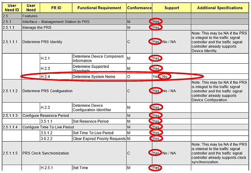
(Extended Text Description: This slide contains a table:
| User Heed ID | User Need | FR ID | Functional Requirement | Conformance | Support | Additional Specifications |
|---|---|---|---|---|---|---|
| 2.5 | Features | |||||
| 2.5.1 | Interface - Management Station to PRS | M | Yes | |||
| 2.5.1.1 | Manage the PRS | M | Yes | |||
| 2.5.1.1.1 | Determine PRS Identity | C | Yes / No / NA | Note: This may be NA if the PRS is integral to the traffic signal controller and the traffic signal controller already supports Device Identity. | ||
| H.2.1 | Determine Device Component Information | M | Yes | |||
| H.2.3 | Determine Supported Standards | M | Yes | |||
| H.2.4 | Determine System Name | O | Yes / No | |||
| 2.5.1.1.2 | Determine PRS Configuration | C | Yes / No / NA | Note: This may be NA if the PRS is integral to the traffic signal controller and the traffic signal controller already supports Device Configuration | ||
| H.2.2 | Determine Device Configuration Identifier | M | Yes | |||
| 2.5.1.1.3 | Configure Reservice Period | M | Yes | |||
| 3.5.1.1 | Set Reservice Period | M | Yes | |||
| 2.5.1.1.4 | Configure Time To Live Period | M | Yes | |||
| 3.5.1.2 | Set Time To Live Period | M | Yes | |||
| 3.6.2.2 | Clear Expired Priority Requests | M | Yes | |||
| 2.5.1 1 5 | PRS Clock Synchronization | C | Yes / No / NA | Note: This may be NA if the PRS is internal to the traffic signal controller and the traffic signal controller already supports clock synchronization. | ||
| H.2.5.1 | Set Time | M | Yes | |||
Note that the word "Yes" is circled in red in all the cells of the Support column, except for the row H.2.4, which is circled "No". The row starting with H.2.4 is also circled in red.)
Slide 94:
Learning Objective #6
Identify a Case Study Specifying Requirements for an SCP System
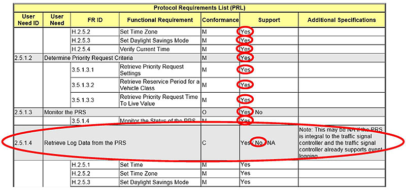
(Extended Text Description: This slide contains a table:
| Protocol Requirements List (PRL) | ||||||
| User Heed ID | User Need | FR ID | Functional Requirement | Conformance | Support | Additional Specifications |
|---|---|---|---|---|---|---|
| H.2.5.2 | Set Time Zone | M | Yes | |||
| H.2.5.3 | Set Daylight Savings Mode | M | Yes | |||
| H.2.5.4 | Verify Current Time | M | Yes | |||
| 2.5.1.2 | Determine Priority Request Criteria | M | Yes | |||
| 3.5.1 3.1 | Retrieve Priority Request Settings | M | Yes | |||
| 3.5.1.3.2 | Retrieve Reservice Period for a Vehicle Class | M | Yes | |||
| 3.5.1 3.3 | Retrieve Priority Request Time To Live Value | M | Yes | |||
| 2.5.1.3 | Monitor the PRS | O | Yes/No | |||
| 3.5.1.4 | Monitor the Status of the PRS | M | Yes | |||
| 2.5.1.4 | Retrieve Log Data from the PRS | C | Yes/No/NA | Note: This may be NA if the PRS is integral to the traffic signal controller and the traffic signal controller already supports event logging. | ||
| H.2.5.1 | Set Time | M | Yes | |||
| H.2.5.2 | Set Time Zone | M | Yes | |||
| H.2.5.3 | Set Daylight Savings Mode | M | Yes | |||
Note that the word "Yes" is circled in red in all the cells of the Support column, except for the last four rows. The row 2.5.1.4 is circled "No". The entire row starting with 2.5.1.4 is also circled in red.)
Slide 95:
Learning Objective #6
Identify a Case Study Specifying Requirements for an SCP System
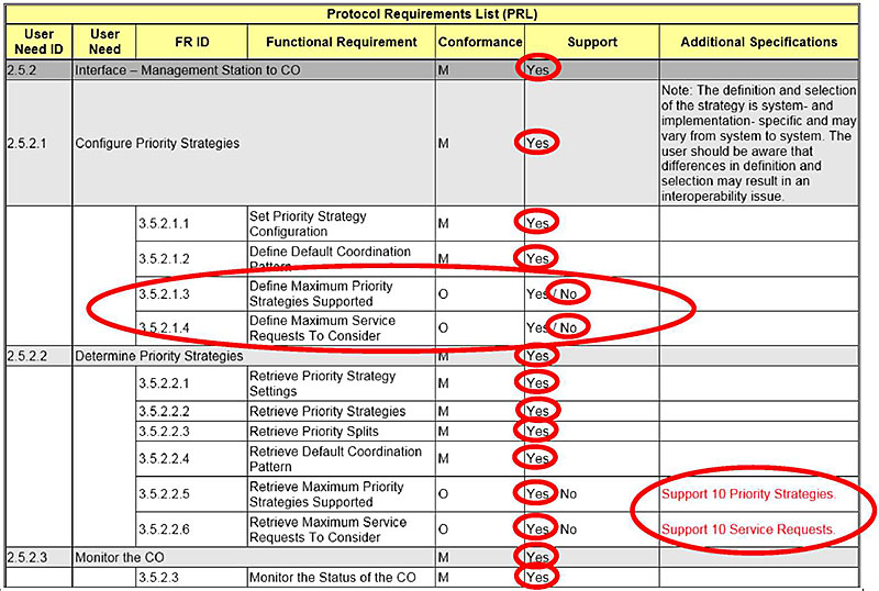
(Extended Text Description: This slide contains a table:
| Protocol Requirements List (PRL) | ||||||
| User Heed ID | User Need | FR ID | Functional Requirement | Conformance | Support | Additional Specifications |
|---|---|---|---|---|---|---|
| 2.5.2 | ||||||
| 2.5.2.1 | Configure Priority Strategies | M | Yes | Note: The definition and selection of the strategy is system- and implementation- specific and may vary from system to system The user should be aware that differences in definition and selection may result in an interoperability issue. | ||
| 3.5.2.1.1 | Set Priority Strategy Configuration | M | Yes | |||
| 3.5.2.1.2 | Define Default Coordination Pattern | M | Yes | |||
| 3.5.2.1.3 | Define Maximum Priority Strategies Supported | 0 | Yes / No | |||
| 3.5.2.1.4 | Define Maximum Service Requests To Consider | 0 | Yes / No | |||
| 2.5.2.2 | Determine Priority Strategies | M | Yes | |||
| 3.5.2.2.1 | Retrieve Priority Strategy Settings | M | Yes | |||
| 3.5.2.2.2 | Retrieve Priority Strategies | M | Yes | |||
| 3.5.2.2.3 | Retrieve Priority Splits | M | Yes | |||
| 3.5.2.2.4 | Retrieve Default Coordination Pattern | M | Yes | |||
| 3.5.2.2.5 | Retrieve Maximum Priority Strategies Supported | 0 | Yes / No | Support 10 Priority Strategies. | ||
| 3.5.2.2.6 | Retrieve Maximum Service Requests To Consider | 0 | Yes / No | Support 10 Service Requests. | ||
| 2.5.2.3 | Monitor the CO | M | Yes | |||
| 3.5.2 3 | Monitor the Status of the CO | M | Yes | |||
Note that the word "Yes" is circled in red in all the cells of the Support column, except for on rows 3.5.2.1.3 and 3.5.2.1.4 which are circled "No." Note that the entire rows 3.5.2.1.3 and 3.5.2.1.4 are also circled in red.)
Slide 96:
What We Have Learned
- The PRL can be used to trace user needs to requirements.
- The "Additional Specifications" column in the PRL can define performance criteria and limits or ranges for functional requirements.
- The RTM traces each requirement to a single design solution, thereby providing for interoperability.
- The design solution consists of a single dialog and one or more objects.
- Developing custom features entails significant effort and risk.
Slide 97:
Resources
- NTCIP 1202 v2.19 - Object Definitions for Actuated Signal Controllers (ASC): https://www.ntcip.org/
- NTCIP 1211 v02 - Object Definitions for Signal Control and Prioritization: https://www.ntcip.org/
- NTCIP 9001 v4 - The NTCIP Guide: https://www.ntcip.org/
- Transit Communications Interface Profiles (TCIP) Standard Development Program: https://www.apta.com/research-technical-resources/standards/technology/apta-tcip-s-001-4-1-1/
- Transit Signal Priority (TSP): A Planning and Implementation Handbook: https://nacto.org/docs/usdg/transit_signal_priority_handbook_smith.pdf
- Transit Communications Interface Profiles (TCIP) Standard Development Program: http://www.aptatcip.com- content is no longer available.
- TCIP Volume 1: http://www.aptatcip.com/Documents.htm- content is no longer available.
Slide 98:
Next Course Modules
ITS Transit Standards Professional Capacity Building (PCB) Program
Module 10: Electronic Fare Payment Systems
and
Module 11: Transit and the Connected Vehicle Environment/Emerging Technologies, Applications, and Future Platforms
Slide 99:
Thank you for completing this module.