Connected and Automated Vehicle Education (CAVe)-in-a-box Infrastructure Kit Assembly Instructions
U.S. Department of Transportation
Intelligent Transportation Systems Joint Program Office
1200 New Jersey Avenue, SE
Washington, DC 20590
PDF Version [4.8 MB]
Table of Contents
BILL OF MATERIALS
CONSTRUCTION
TABLE OF FIGURES
Bill of Materials
- Travel case.
- Traffic signal controller (TSC).
- LAN network switch.
- Vehicle-to-everything (V2X) Hub computer or Intel NUC computer.
- Roadside Unit (RSU).
- Three N-male to N-female LMR-400 Coaxial Cable.
- Two 6 dBi omnidirectional antenna.
- GPS antenna.
- Tablet.
- Tablet mount assembly.
- Cradlepoint router.
- Power over Ethernet (PoE) injector.
- Ethernet cables – 2 ft.
- Hardware – cap screws.
Note: If you are constructing the kit on your own, double-sided hook and loop fasteners are an acceptable means to fasten components. For our purposes and shipping concerns, all in-house kits have their devices mechanically fastened with cap screws.
Construction
- Begin with a blank shelf (figure 1). This is the basis for building both the component shelf and the traffic controller shelf.
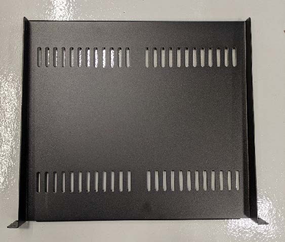
Source: FHWA
Figure 1. Photo. Component shelf.
V2X Computer Style 1
- The first item mounted is the V2X Hub computer. The four mounting holes for the fan cover are modified to attach the device to the component shelf. Refer to figure 2.
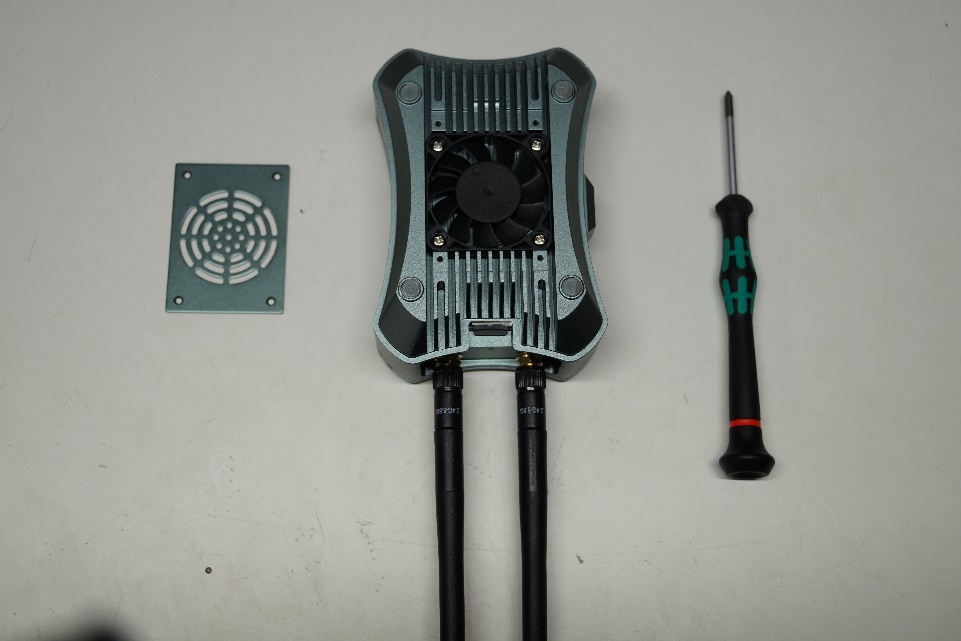
Source: FHWA
Figure 2. Photo. Computer fan cover.
- Mounting holes are drilled into the computer, around the fan, to allow for a 4–40 thread. Refer to figure 3.
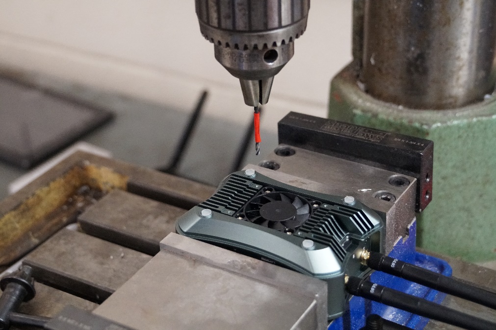
Source: FHWA
Figure 3. Photo. Drilling the computer.
- Measurements are taken for best placement on the component shelf. Figure 4 shows placement of the V2X Hub computer.
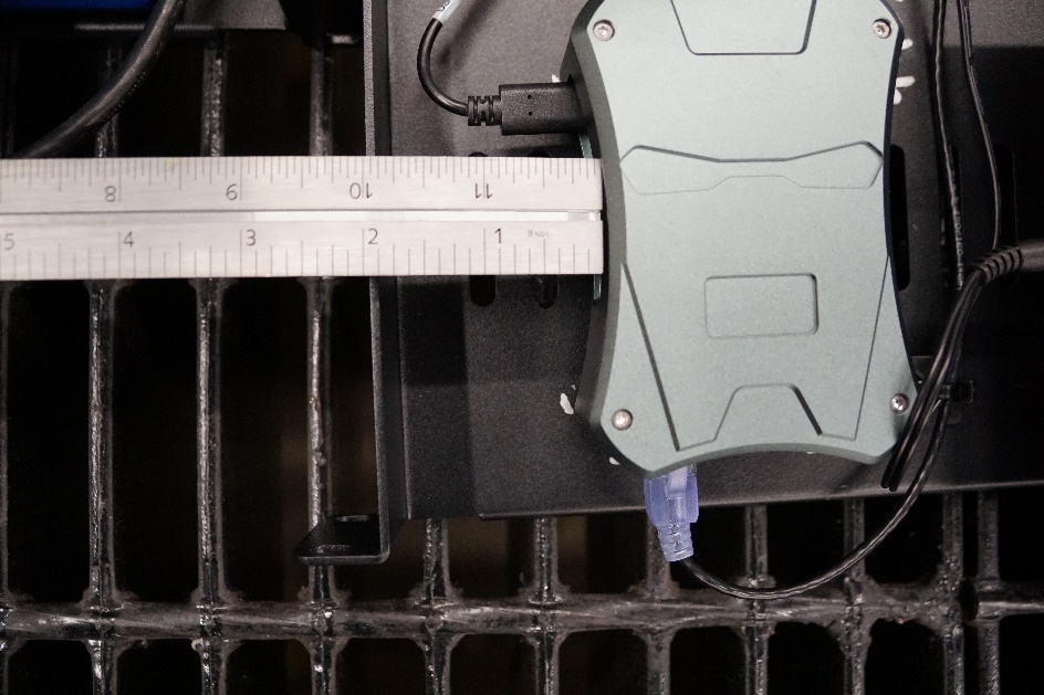
Source: FHWA
A. Measuring from the left of the V2X Hub computer.
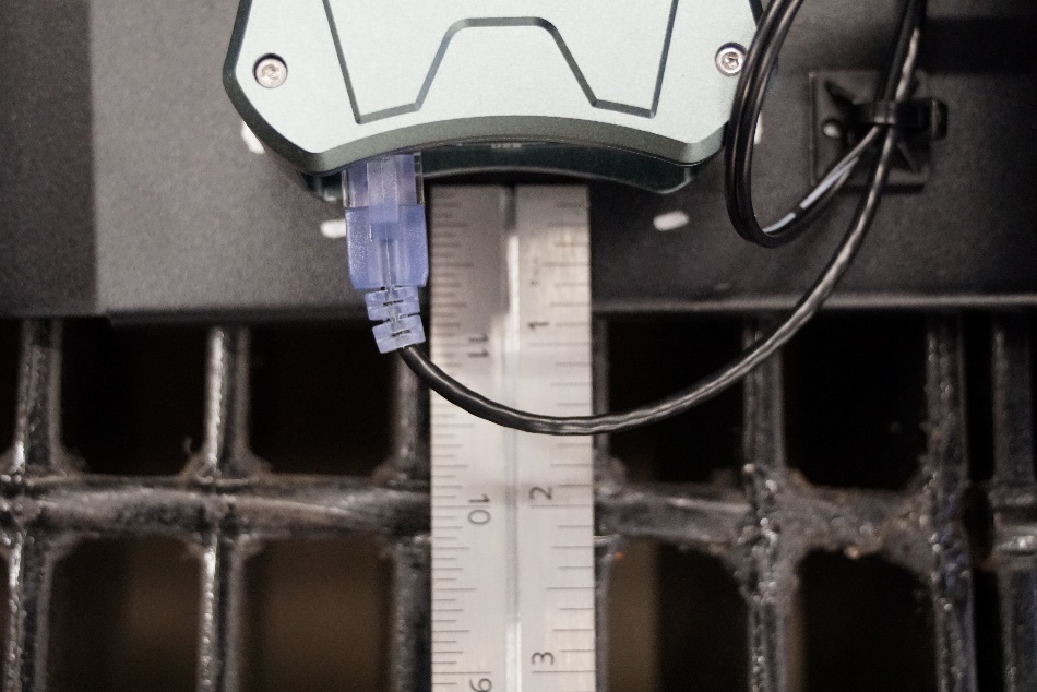
Source: FHWA
B. Measuring from the bottom of the computer
Figure 4. Photos. Measuring the placement.
- Use the fan cover and a center punch to mark the locations of the holes on the component shelf (figure 5).
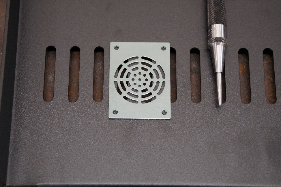
Source: FHWA
Figure 5. Photo. Center punching.
- Mount the V2X Hub computer to its final placement on the component shelf. Refer to figure 6 for proper placement.
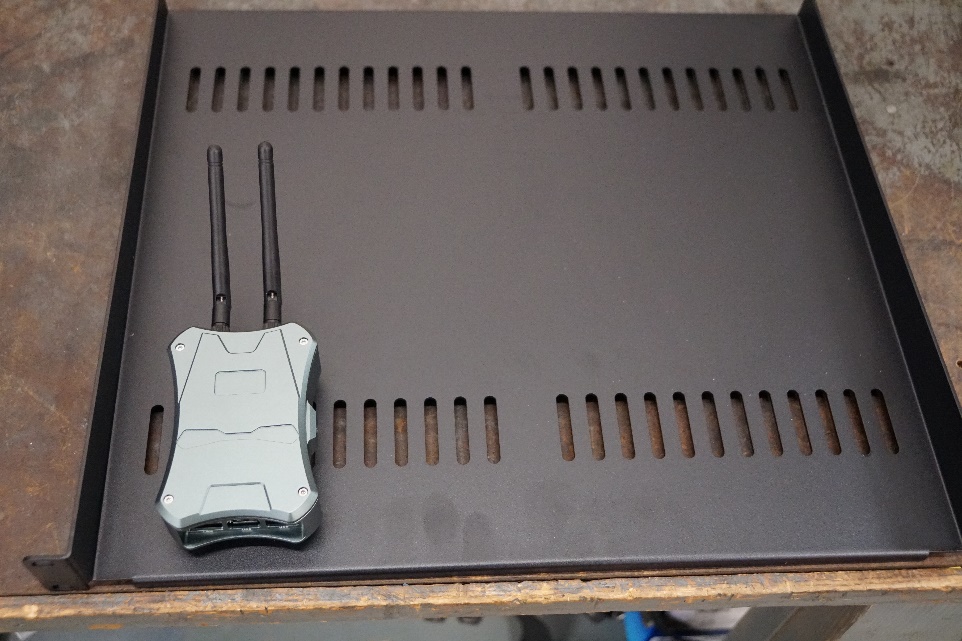
Source: FHWA
Figure 6. Photo. V2X Hub computer final placement.
V2X Computer Style 2
- A NUC computer may be used in lieu of a V2X Hub computer (figure 7).
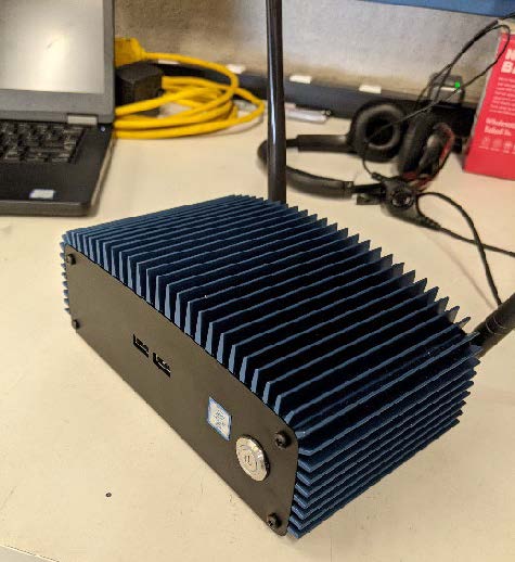
Source: FHWA
Figure 7. Photo. NUC computer.
- To mount, the bottom plate of the NUC computer must be removed as well as the solid-state drive (SSD) that is attached. Holes need to be drilled and tapped three-fourths of an inch from the end with the SSD connectors, and three-eighths of an inch from the other side. This is to provide clearance of contacting the SSD. Refer to figure 8 for hole placement.
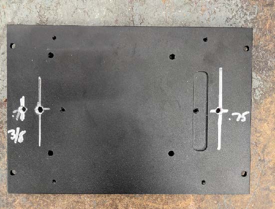
Source: FHWA
Figure 8. Photo. NUC computer hole placement.
- Use the holes you just drilled and a center punch to match hole placement to the shelf (see figure 9).
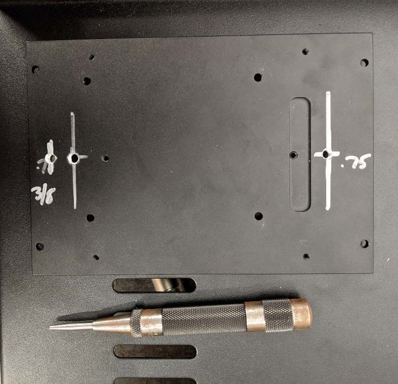
Source: FHWA
Figure 9. Photo. NUC center punching.
Tablet Mount
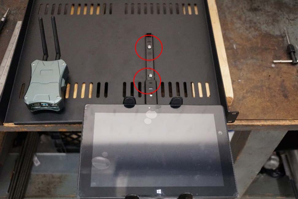
- It is critical to use the tablet as a locator for mounting the tablet mount assembly to the shelf (see figure 10).
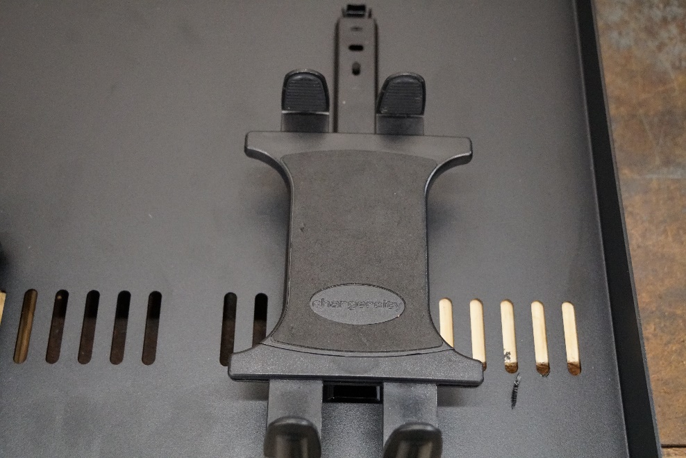
Source: FHWA
Figure 10. Photo. Tablet mount assembly.
- Attach the tablet to the center of the mount (figure 11).
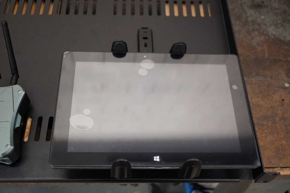
Source: FHWA
Figure 11. Photo. Tablet placement.
- Center the assembly between the edge of the shelf and the V2X Hub computer. The tablet mount is mounted using 10-24 screws threaded into the shelf (figure 12).
Source: FHWA
Figure 12. Photo. Centered and threaded mount.
Cradlepoint Router
- Following the tablet mount assembly is the Cradlepoint router. The rear face of the router is mounted flush with the edge of the shelf. This device is secured with 8-32 screws threaded into the shelf. Refer to figure 13.
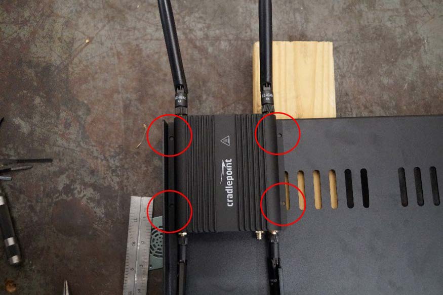
Source: FHWA
Figure 13. Photo. Router mounted at the corner of the shelf.
Network Switch
- The network switch is mounted adjacent to the Cradlepoint. It is also mounted flush with the back edge of the shelf (figure 14).
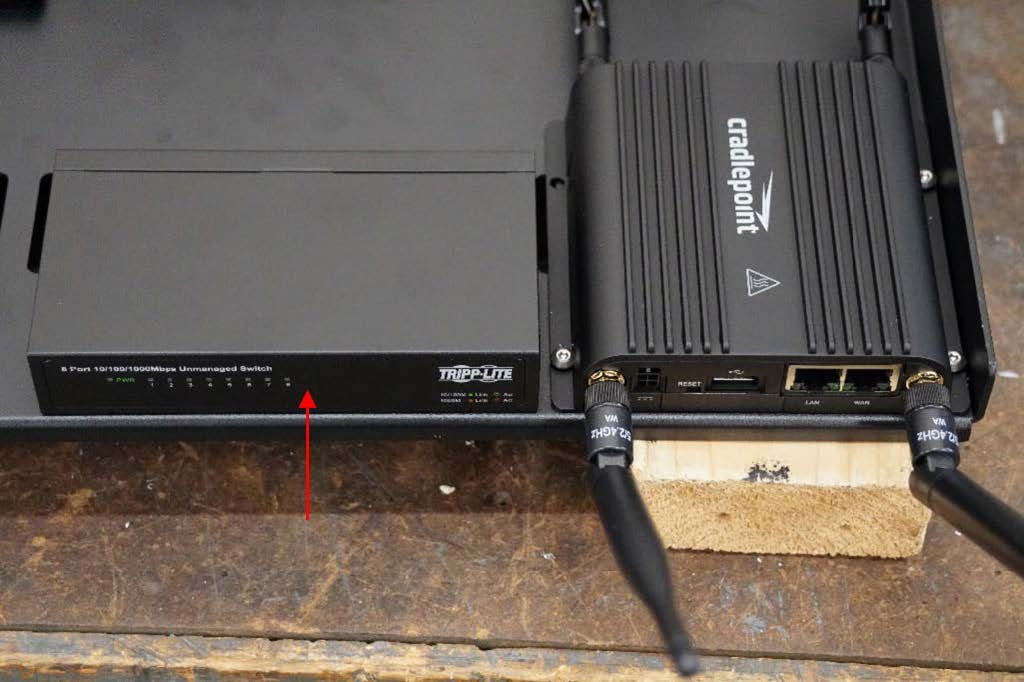
Source: FHWA
Figure 14. Photo. Network switch placement.
- The network switch is mounted to the shelf utilizing the mounting holes circled. M3 screws are required for fastening. Refer to figure 15.
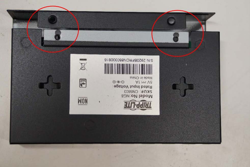
Source: FHWA
Figure 15. Photo. Network switch mounting holes placement.
PoE Injector
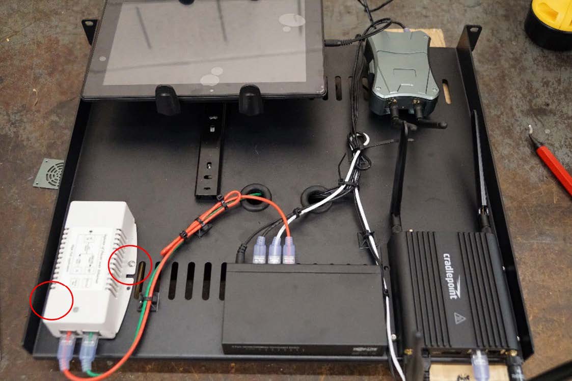
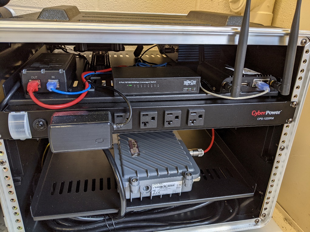
- Lastly, the PoE Injector, shown as the bottom-left device in figure 16, is mounted offset from the edge of the shelf using 6-32 screws with threads tapped into the shelf. The circles on the image indicate the screw locations. An example of cable routing is also shown in figure 16.
Source: FHWA
Figure 16. Photo. PoE injector placement.
Traffic Controller
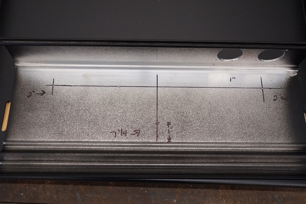
- Remove the bottom panel from the traffic controller to drill three holes. Holes are drilled and tapped for 10-24 screws, see figure 17 below for hole positioning.
Source: FHWA
Figure 17. Photo. Distances for holes on traffic controller (bottom).
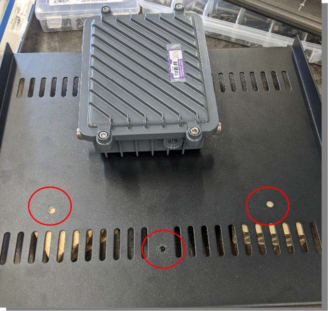
- Utilizing the bottom of the traffic controller for placement, mark and drill holes into the shelf to secure the traffic controller to the shelf, refer to figure 18.
Source: FHWA
Figure 18. Photo. Holes drilled in shelf for TSC mounting.
- The TSC and RSU are both mounted on the lower shelf of the box for better stability of the kit. Mount the TSC at the edge of the shelf (figure 19).
Source: FHWA
Figure 19. Photo. TSC mounted at the front of the shelf.
Road-side Unit
- The RSU is mounted roughly centered on the lower shelf near the backside to allow the TSC to fit (figure 20).
Source: FHWA
Figure 20. Photo. Mounted RSU.
Box Assembly
- Secure the upper shelf with Cradlepoint router, tablet, and other components in the upper portion of the travel case with included screws (figure 21).

Source: FHWA
Figure 21. Photo. Upper shelf mounted.
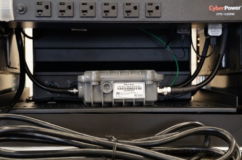
- Secure power strip to travel case immediately below the upper shelf to allow clearance for TSC (figure 22).
Source: FHWA
Figure 22. Photo. Power strip mounted below upper shelf.
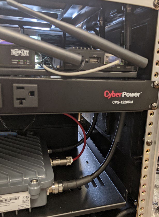
- Plug in the power cables to the power strip and secure the cabling so it is neat and out of the way. An example of this can be seen below in figure 23.
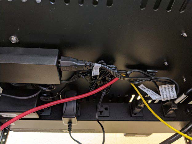
Source: FHWA
Figure 23. Photo. Power cables secured to the bottom of the shelf.
- Attach the lower shelf with the TSC and RSU lower in the case, connecting RSU power once it is attached (figure 24).
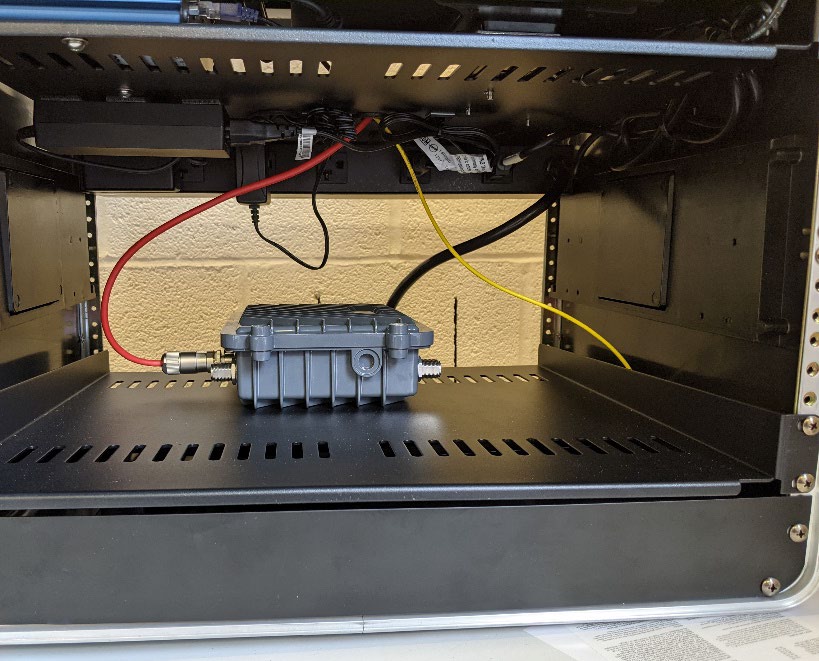
Source: FHWA
Figure 24. Photo. Shelf with RSU mounted.
Antenna Mounting
- The final step is to run the LMR-400 coaxial cables from the RSU to the outside of the travel case. See figure 25 to see the mentioned cables.

Source: FHWA
Figure 25. Photo. Cables from RSU to outside of travel case.
- The hole placement for the RSU antenna is estimated by the path that allows the cables in figure 23 to reach the top of the case in a straight path. The holes are drilled to a diameter of five-eighths of an inch with a step drill bit. Refer to figure 26 to see cables reaching the top of the travel case.
Source: FHWA
Figure 26. Photo. RSU antenna cables.
- Antenna are mounted on the outside for the RSU to not be inhibited. Refer to figure 27 below.
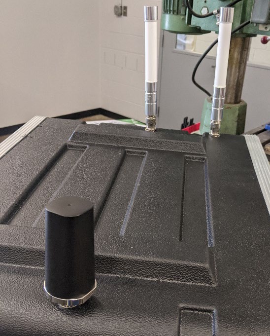
Source: FHWA
Figure 27. Photo. Antenna mounted outside of the travel case.
Completed Box
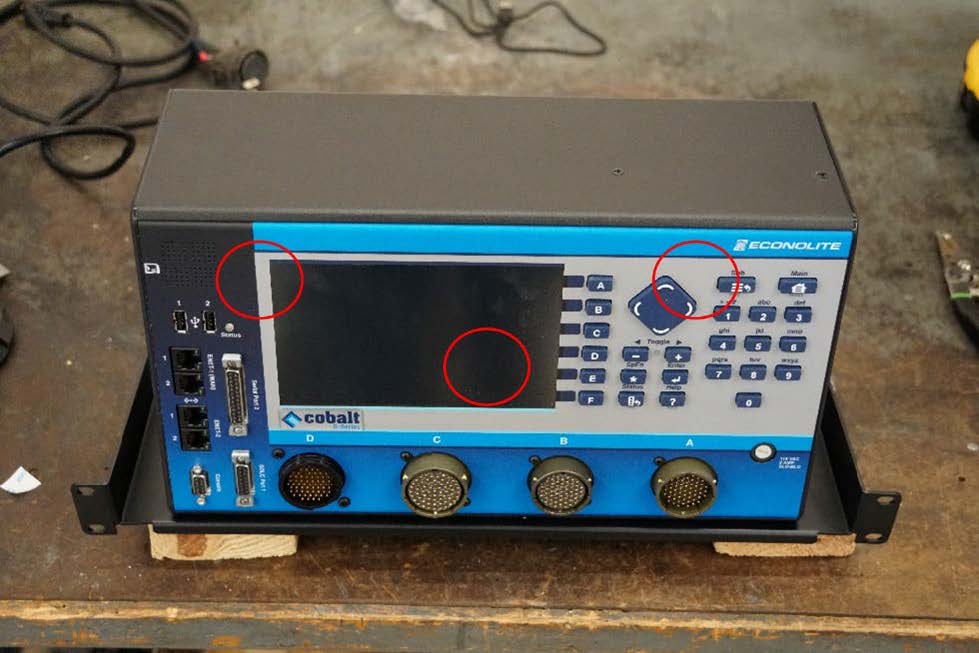
- Connect the ethernet and power cables the traffic controller. Refer to figure 28 to see the final cable connections and finished CAVe-in-a-box unit.
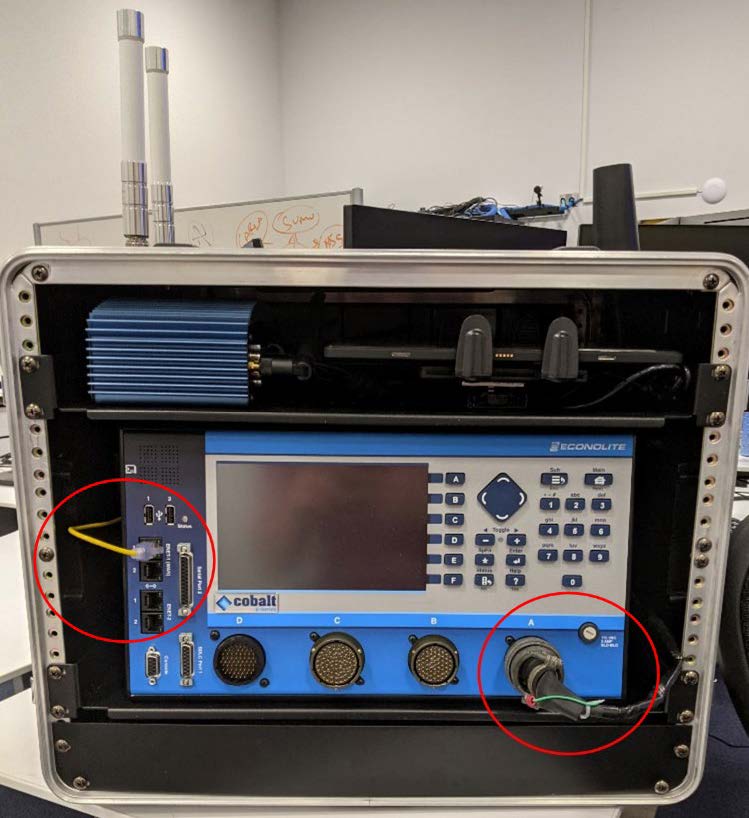
Source: FHWA
Figure 28. Photo. Completed cabinet.
Return to top